Tri Power X33 Mod HP Manual | Rev 1.20 | © Alpha Technologies GmbH 2013
Operating
a
nd Main
tena
nce
Manua
l
Tri Power X33 Mod HP
31
5.2
Electrical connections
The electrical connection of the UPS to the switchboard is part of the installation and is usually done by the user and not
by the UPS manufacturer; therefore the following indications are purely an example and the actual electrical connections
must be done in accordance with local standards.
Once the UPS has been removed from the packaging and positioned in its final place of installation, the authorised tech-
nician can start the installation.
ATTENTION
Before starting please read and apply the following with attention. It is strictly forbidden to proceed with installati-
on if one or more of the following conditions have not been checked.
1. Do not proceed with installation if there is water or moisture.
2. Remember that opening or removing the panels from the UPS you risk exposure to high and dangerous voltages.
3. Check there is no mains voltage on the equipment.
4. Check that the loads are off and disconnected from the UPS;
5. Check that the UPS is off and not live.
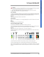
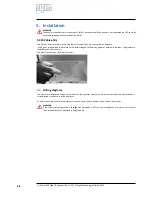
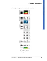
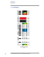
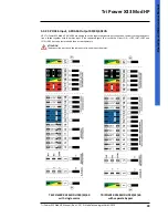
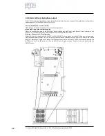
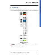
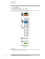
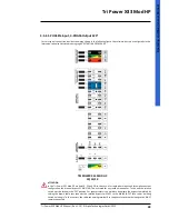
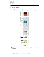
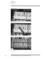
All the electrical connection operations are done working on the distribution box. The fuse carriers, output switch and
manual bypass switch are on the outside of the box while inside you will find the terminal block on which to do the con-
nections.
5.2.2 Preliminary operations
Before connecting the UPS make sure that:
1.
mains voltage (volt V in input) and frequency correspond to the values on the UPS rating plate;
2.
earthing complies with the IEC standards (International Electronic Commission) or local regulations;
3.
the electrical system is equipped with all the necessary differential protections and thermal circuit breakers
upstream from the UPS input.
5.2.3 Connection the load
Before actually starting to connect the loads make sure the rated power of the UPS (OUTPUT POWER) indicated on its
rating plate is equivalent to or greater than the total sum of the load powers.
INDICATION
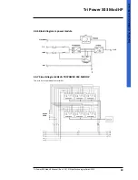
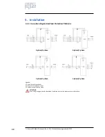
The loads wiring diagram is in the DIAGRAMS chapter.
The characteristics of the output cables must conform to the sections of the cables indicated in table 5 of the TABLES
chapter.
A separate switchboard must be supplied for the load. It is a good idea to use isolating switches or thermal circuit brea-
kers conforming to the IEC standards to protect the lines leading from the electrical panel.
Use adhesive labels or similar to indicate the following values on the system’s general panel:
maximum rated power of the total load;
maximum rated power of the load at power intakes.
if an ordinary switchboard is used (outlets for mains voltage and for the UPS), make certain that there is an indicati-
on of the voltage applied on each outlet (‘Mains’ or ‘UPS’).
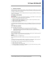
5.2.1 Safety recommendations


