SNQ-60x0-320F Series Data Center Switch
Hardware Installation Guide
4
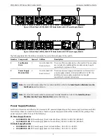
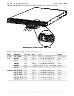
The following table lists the LED indicators available on the front panel of the switch.
Number
LED Indicator
Color
Behavior
Description
1
STAT
Green
Solid Light
POST passed. Normal operation.
Blinking
POST in progress.
Off
Power off.
Amber
Blinking
POST, power supply, or fan module failed. System
too hot.
2
MGMT
Green
Solid Light
Connection is active.
Blinking
Packets transmitted and received.
Off
No connection detected. Port is disabled.
3
PWR
Green
Solid Light
Power on
Off
Power off. No power cable attached.
Amber
Blinking
Power supply failure. Voltage, Current, or
Temperature is too high.
4
Console
Green
Solid Light
Console is on.
Off
Console is off.
5
Link/Activity/Speed
(Ports 1-48, 53-100)
Green
Solid Light
Secure 40 Gbps connection is active.
Blinking
Packets transmitted and received.
Off
No active connection or port disabled.
Amber
Solid Light
Secure 10 Gbps connection is active.
Blinking
Packets transmitted and received.
Off
No active connection or port disabled.
Link/Activity/Speed
(Ports 49-52, 101-104)
Green
Solid Light
Secure 40 Gbps connection is active.
Blinking
Packets transmitted and received.
Off
No active connection or port disabled.
6
FAN 1, 2, 3, 4, 5
Green
Solid Light
Diagnostics passed. Normal operation.
Off
Not receiving power.
Amber
Blinking
Fan failure.
7
Locator
Blue
Blinking
Locator function is enabled
Off
Locator function is disabled.
Note:
For more information about supported QSFP+ transceivers and transceiver installation, refer to the
Installing Transceivers into the Transceiver Ports
section later on.
Back Panel Components
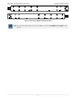
The back panel of switches in this series features the following components:


