background image

SNQ-60x0-320F Series Data Center Switch 

Hardware Installation Guide 

14 

Installing Power Modules into the Power Module Slots 

Switches in this series can have 2 redundant power supplies installed. When the one power supply fails, the second 
power supply will automatically take over the power supply responsibilities until the faulty power supply has been 
replaced. 

Installing an AC Power Supply Module 

This section will assist administrators with the installation and replacement of AC power supply modules in this switch. 
On the back panel of the switch, there are two power supply module slots. 


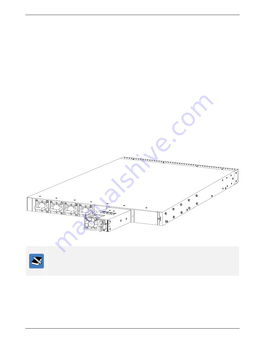
The figure below illustrates how to properly install an AC power supply module. 

1.


It is important to make sure which 

airflow direction

 is used in this switch. Have a look at the fan modules 

installed and make sure that the AC power supply module supports the same airflow direction. The airflow 
direction can either be 

front-to-back

 or 

back-to-front

 airflow. 

2.


Remove the power supply module slot’s protective cover by simply pulling the lever attach to it. The cover 
should come off without any difficulty. 

3.


Insert the AC power supply module, without an AC power cord supplying power, into the power supply 
module slot. Make sure that the AC power supply module is inserted all the way until the clip clicks into place. 

4.


Connect one end of the AC power cord, included in the package, into the grounded electrical outlet at the site 
and insert the other end of the AC power cord into the AC power port of the AC power supply module. The 
switch will automatically adjust the voltage supplied to the voltage needed as this power supply supports any 
voltage power supply in the range from 100VAC to 240VAC at 50Hz to 60Hz. 


Figure 5-7 Installing an AC Power Supply Module (Before) 


Note:

 By default, only one power supply module is installed in the second power supply module slot. The 

open power supply module slot will be covered with a panel. When purchasing a second power 
supply module, make sure that the airflow of the new power supply module functions in the same 
direction as the existing power supply module. Never leave an open power supply module slot 
open, without a cover panel, as this will negate the airflow within the switch. 


Содержание SNQ-60x0-320 Series

Страница 1: ...SNQ 60x0 320 Series Data Center Switch Hardware Installation Guide...

Страница 2: ...ot expressly approved by the party responsible for compliance could void the user s authority to operate the equipment CE Mark Warning This is a Class A product In a domestic environment this product...

Страница 3: ...ts 6 Hardware Installation 8 Installation Guidelines 8 Installation using the Rubber Feet 8 Installation into a Rack 8 Installing Transceivers into the Transceiver Ports 12 Installing Power Modules in...

Страница 4: ...es Quick Installation Guide Typographical Conventions Throughout this document certain typographical conventions will be used to either emphasize information or represent the features that this switch...

Страница 5: ...d only by the CPU used The SNQ 6070 320F uses the Freescale CPU and the SNQ 60A0 320F uses the Intel CPU Package Contents After purchasing any of the switches in this series the following items will b...

Страница 6: ...sed to perform a factory reset of the software loaded on this switch 2 One Out Of Band micro USB type B console port When both console ports are active this port will have the priority 3 One Out Of Ba...

Страница 7: ...1 48 53 100 Green Solid Light Secure 40 Gbps connection is active Blinking Packets transmitted and received Off No active connection or port disabled Amber Solid Light Secure 10 Gbps connection is act...

Страница 8: ...rately to improve redundancy Note For more information about fan module installation refer to the Installing Fan Modules into the Fan Module section later on Note For more information about power supp...

Страница 9: ...an be channeled either from the front of the switch to the back of the switch front to back airflow or from the back of the switch to the front of the switch back to front airflow When airflow is prop...

Страница 10: ...ies Data Center Switch Hardware Installation Guide 7 Figure 4 5 Side Panels of SNQ 60x0 320F Series Switch Note For more information about rack mount installation refer to the Installation into a Rack...

Страница 11: ...each rubber foot and then attach the foot into the appropriately marked square The rubber feet cushion the switch protecting the casing from scratches and preventing it from scratching other surfaces...

Страница 12: ...attach the switch onto to the rack mount unit and are not included in the switch s packaging as rack mount units differ at each installation site The figure below illustrates how to install the front...

Страница 13: ...mount unit at the appropriate height The ears of the bracket must be facing backwards and outwards 6 Use the rack mount unit screws and the additional screwdriver to fasten the bracket onto the back...

Страница 14: ...ts 8 Position the switch so that the rack mount slider brackets align horizontally within the two rows of rack mount slider bracket pegs found on the side panel of the switch 9 Slide the switch carefu...

Страница 15: ...tion from 10 to 40 Gigabit Ethernet infrastructures in data centers Each of the switch s QSFP ports can operate in either the native 40 Gigabit Ethernet mode or the 4 times 10 Gigabit Ethernet mode Th...

Страница 16: ...40 Gbps Direct Attached Cable Passive 1 meter 2053638 3 QSFP 40 Gbps Direct Attached Cable Passive 3 meters 2053638 5 QSFP 40 Gbps Direct Attached Cable Passive 5 meters 2053453 4 QSFP 4 x 10 Gbps 1...

Страница 17: ...y simply pulling the lever attach to it The cover should come off without any difficulty 3 Insert the AC power supply module without an AC power cord supplying power into the power supply module slot...

Страница 18: ...airflow direction is used in this switch Have a look at the fan modules installed and make sure that the DC power supply module supports the same airflow direction The airflow direction can either be...

Страница 19: ...ll the lever backwards Installing Fan Modules into the Fan Module Slot This section will assist administrators with the installation and replacement of fan modules in this switch On the back panel of...

Страница 20: ...Fan Module into the Fan Module Slot Before The figure below illustrates how the back panel will look with 4 fan modules properly installed Figure 5 12 Installing Fan Module into the Fan Module Slot A...

Страница 21: ...y Buffer Size 12 MB Shared Number of MAC Addresses 32 000 Min 288 000 Max Routing Table IPv4 16 000 Min 112 000 Max IPv6 8 000 Min 56 000 Max Layer 2 Multicast 16 000 VLAN Entries 4 000 ACL Entries 4...

Страница 22: ...ans at Low Speed 59 50 dBA All Fans at High Speed 76 10 dBA Environment Dimensions 44mm H x 440mm W x 487 4mm D Weight 9 29 kg with 2 AC PSUs and 5 Fans installed Operating Temperature 0 C to 45 C 32...

Страница 23: ...SNQ 60x0 320F Series Data Center Switch Hardware Installation Guide 20 Specification Description FCC CFR47 Part 15B Class A ICES 003 Class A CNS 13438 Class A GB9254 YDT993...

Страница 24: ...your facilities manager or a qualified electrician if you are not sure what type of power is supplied to your building Not all power cords have the same current ratings Do not use the power cord provi...

Страница 25: ...rcuit Overloading Consideration should be given to the connection of the equipment to the supply circuit and the effect that overloading of the circuits might have on overcurrent protection and supply...

Страница 26: ...to Back Airflow 460 Watt Fan 4 x Fan Modules Front to Back Airflow 1 x AC 460W 12V FB 4 x FAN 17000 FB SNQ 60A0 320F AB B CPU Intel CPU PSU 1 x AC Power Supply Back to Front Airflow 460 Watt Fan 4 x F...

Страница 27: ...SNQ 60x0 320F Series Data Center Switch Hardware Installation Guide 24 Part Number Description FAN 17000 FB Fan Module Front to Back Airflow FAN 17000 BF Fan Module Back to Front Airflow...

Отзывы: