SNQ-60x0-320F Series Data Center Switch
Hardware Installation Guide
16
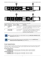
Figure 5-9 Installing a DC Power Supply Module (Before)
The figure below illustrates how the back panel will look with a DC power supply module properly installed.
Figure 5-10 Installing a DC Power Supply Module (After)
When installing a DC power supply module, ground the chassis before connecting the switch to the DC power source.
Use a minimum of 18 AWG stranded copper wire for grounding. The wire should be long enough to reach from the
installed switch to the facility ground point.
To remove the DC power supply module, remove the DC power cord and then press the clip to the left and pull the
lever backwards.
Installing Fan Modules into the Fan Module Slot
This section will assist administrators with the installation and replacement of fan modules in this switch. On the back
panel of the switch, there are five fan module slots.
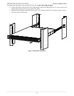
The figure below illustrates how to properly install a fan module.
1.
It is important to make sure which
airflow direction
is used in this switch. Have a look at the power supply
module(s) installed and make sure that the fan modules support the same airflow direction. The airflow
direction can either be
front-to-back
or
back-to-front
airflow.
2.
Remove the fan module slot’s protective cover by simply pulling the lever attach to it. The cover should come
off without any difficulty.
3.
Insert the fan module into the fan module slot. Make sure that the fan module is inserted all the way until the
clip clicks into place.

