


218
Rockwell Automation Publication 2198-UM002E-EN-P - February 2018
Chapter 7
Troubleshoot the Kinetix 5700 Drive System
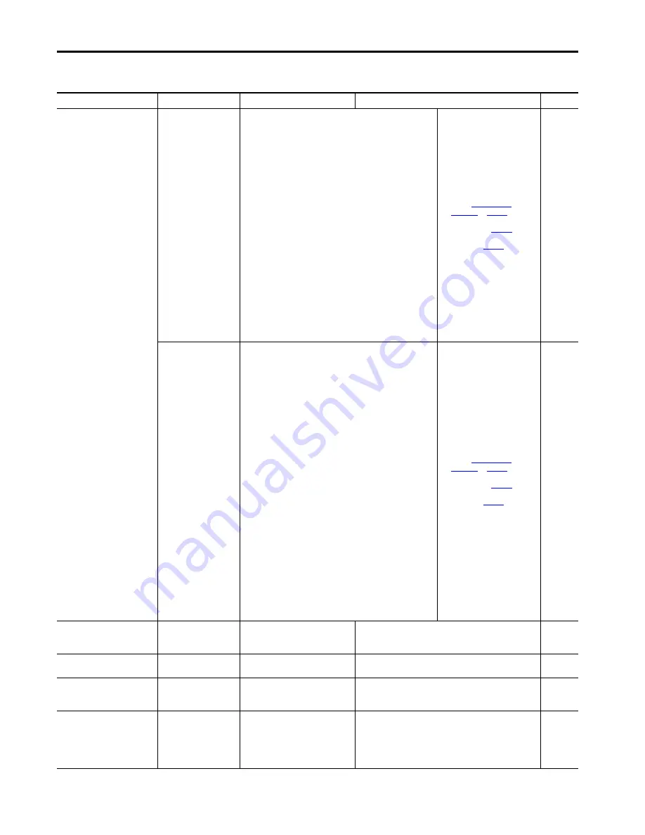
FLT S47 – FDBK DEVICE FAILURE
nn
Motor Feedback Device
Failure Fault
(DSL feedback)
The DSL feedback device has detected an internal error.
The nn sub-code is defined as follows:
01: ACCELERATION OVERFLOW
04: TRACKING FILTER ERROR
05: VECTOR LENGTH ERROR
06: COUNTER ERROR
07: SYNCHRONIZATION ERROR
16: SINGLE TURN ERROR
17: MULTI TURN AMPLITUDE ERROR
18: MULTI TURN SYNC ERROR
19: MULTI TURN VECTOR LENGTH ERROR
35: STANDARD PARAMETER ERROR
36: INTERNAL COMMUNICATION ERROR1
37: INTERNAL COMMUNICATION ERROR2
38: INTERNAL SYSTEM ERROR
48: CRITICAL TEMPERATURE
49: CRITICAL LED CURRENT
50: CRITICAL SUPPLY VOLTAGE
51: CRITICAL SPEED
52: CRITICAL ACCELERATION
53: COUNTER OVERFLOW
54: INTERNAL MONITORING ERROR
66: INTERNAL RESOURCE ACCESS ERROR
88: POSITION OUT OF RANGE
• Check motor feedback cable for
proper connectivity and
continuity
• Check motor phasing (U, V, W)
and DSL feedback 2-pin wire
connections at the drive
• Review
– See bonding painted panels
– See wire-braid bonding on
• Cycle control power
• Check feedback shield
connection
• Reduce shock and vibration to
motor
• Replace motor if fault continues
Inverters
Motor Feedback Device
Failure Fault
(Hiperface feedback)
The Hiperface feedback device has detected an internal error.
The nn sub-code is defined as follows:
01: INCORRECT ALIGNMENT DATA
02: INCORRECT INTERNAL ANGULAR OFFSET
03: DATA FIELD PARTITIONING TABLE DESTROYED
04: ANALOG LIMIT VALUES NOT AVAILABLE
05: INTERNAL I2C BUS INOPERATIVE
06: INTERNAL CHECKSUM ERROR
07: ENCODER RESET OCCURRED AS A RESULT OF PROGRAM MONITORING
08: COUNTER OVERFLOW
09: PARITY ERROR
10: CHECKSUM OF TRANSMITTED DATA IS INCORRECT
11: UNKNOWN COMMAND CODE
12: NUMBER OF TRANSMITTED DATA IS INCORRECT
13: TRANSMITTED COMMAND AGRUMENT IS NOT ALLOWED
14: THE SELECTED DATA FIELD MAY NOT BE WRITTEN TO
15: INCORRECT ACCESS CODE
16: SIZE OF SPECIFIED DATA FIELD CANNOT BE CHANGED
17: SPECIFIED WORD ADDRESS LIES OUTSIDE THE DATA FIELD
18: ACCESS TO NON-EXISTENT DATA FIELD
28: VALUE MONITORING OF THE ANALOG SIGNALS (process data)
29: TRANSMITTER CURRENT CRITICAL
(contamination, transmitter breakage)
30: ENCODER TEMPERATURE CRITICAL
31: SPEED TOO HIGH, NO POSITION FORMATION POSSIBLE
32: SINGLETURN POSITION UNRELIABLE
33: MULTITURN POSITION ERROR
34: MULTITURN POSITION ERROR
35: MULTITURN POSITION ERROR
• Check motor feedback cable for
proper connectivity and
continuity
• Check motor phasing (U, V, W)
and Hiperface feedback 15-pin
wire connections at the drive
• Review
– See bonding painted panels
– See wire-braid bonding on
• Cycle control power
• Check feedback shield
connection
• Reduce shock and vibration to
motor
• Replace motor if fault continues
Inverters
FLT S49 – BRAKE SLIP FLT
Brake Slip Exception
Motor displacement exceeded the brake
slip tolerance while the mechanical brake
was engaged.
Check motor brake.
Inverters
FLT S50 – POS HW OTRAVEL
Hardware Overtravel -
Positive
The axis has moved beyond the digital
input travel limit in the positive direction.
Check digital input and axis position.
Inverters
FLT S51 – NEG HW OTRAVEL
Hardware Overtravel -
Negative
The axis has moved beyond the digital
input travel limit in the negative
direction.
Check digital input and axis position.
Inverters
FLT S54 – POSN ERROR
(5)
Excessive Position Error Fault
The position error of the position control
loop has exceeded the value given by
Position Error Tolerance for a time period
given by Position Error Tolerance Time.
• Check position loop tuning
• Increase the feedforward gain
• Verify sizing of the drive and motor
• Check motor power wiring
• Increase Position Error Tolerance and/or Position Error Tolerance
Time attribute values
Inverters
Table 95 - FLT S
xx
Fault Codes (continued)
Exception Code on Display
Exception Text
Problem
Possible Solutions
Module