background image

2-16

Malfunctions with Indications

VP-14

SCR Overtemp
(Selectable)
(Parameter 101
bit 4 when
Parameter
630=1)

This fault occurs when the thermal switch mounted
on the heat sink remains open for 1 time specified
by parameter 726. The switch is designed to open
above a temperature of 85 degrees C. This fault is
type selectable as either Soft or Warning. A Soft
Fault selection will cause a controlled stop to be
initiated.

The fault is caused by excessive heating of the drive heat
sink. Below are a list of things that may have contributed to
the occurrence of the fault.
1. The ambient air temperature around the drive has

exceeded the 60 degrees C rating. Determine the cause
of the excessive ambient temperature and correct. Allow
the drive to cool prior to executing a Clear Fault and
continuing.

2. The failure of cooling fans if the drive is so equipped.

Verify that all fans are fully operational and that the air
flow to the fans is not obstructed or restricted in any way.
Execute a Clear Fault when the heat sink temperature has
been reduced to the point where the switch has closed.

3. The output rating of the drive has been exceeded which

has caused excessive heat build up in the heat sink. Verify
that the drive output rating is correct for the application.
Allow the drive to cool and execute a Clear Fault to
continue operation.

4. The Heat Sink Thermal switch (HST) or associated circuit

malfunction. Remove all power to the drive. Check the
connections to the switch which is located in the middle of
the heat sink. Check, in a cool ambient, that the switch is
closed by measuring the resistance between the two
terminals, replace switch if found inoperative. If the fault
occurs again replace the Main Control Board.

5. On MkVA & HkVA drives, check the vane switch assembly.

VP-15

External
Overtemp
(Selectable)
(Parameter 101
bit 5 when
Parameter
630=1)

This fault occurs when the motor temperature
discrete input (TB3-1 & 2) is low for a time greater
than specified in parameter 725. This discrete input
is usually connected to an internal thermal switch
in the motor. It could however be connected to any
normally closed switch external to the drive. One
second after the switch opens the drive will fault.
This fault is type selectable as either Soft or
Warning. A Soft Fault selection will cause a
controlled stop to be initiated.

Correct the condition which caused the external switch to
open. Execute a Clear Fault and continue operation. If this
input is not used, connect it to the appropriate control
voltage to eliminate Warning Fault occurrences.

VP-16

Thermal
Overload
Pending
(Warning)
(Parameter 101
bit 6 when
Parameter
630=1)

This fault will be issued any time the average motor
armature current exceeds the level specified by
720 “Ovld Pend Level.” It is used to indicate that the
present armature current output exceeds the level
specified by the user and continued operation at
this level may cause damage to the motor and/or
process. This fault can be disabled. Refer to
parameter 632.

No action is required for continued operation. However,
depending on the application it may be useful to monitor this
fault and take action to reduce the current output when it
occurs.

Note that a malfunctioning encoder could cause a VP-16
and a VP-39 as well.

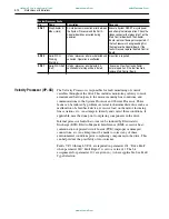
Velocity Processor Faults

No.

Name

Description

Recovery

Aotewell Ltd  industry-mall.net

www.aotewell.com

[email protected]

www.aotewell.com

Содержание 1395

Страница 1: ...Troubleshooting Guide 1395 Digital DC Drive Aotewell Ltd industry mall net www aotewell com sales aotewell com www aotewell com ...

Страница 2: ...ative purposes Because of the many variables and requirements associated with any particular installation Rockwell Automation Inc cannot assume responsibility or liability for actual use based on the examples and diagrams No patent liability is assumed by Rockwell Automation Inc with respect to use of information circuits equipment or software described in this manual Reproduction of the contents ...

Страница 3: ...eral 3 1 Logic Control Malfunctions 3 1 Link Configuration Parameter Malfunctions 3 3 Velocity Control Malfunctions 3 3 Velocity Feedback Device Malfunction 3 9 Encoder Device Malfunction 3 9 Analog Tachometer Malfunction 3 13 Armature Current Control 3 15 Main Control Board Test Points 3 16 Field Current Control 3 19 Magnetics Power Structure 3 22 Series A 3 22 Series B 3 29 Auto Tuning Malfuncti...

Страница 4: ...t Points General 6 1 Main Control Board 6 1 Power Stage Interface Switcher Board 6 3 Power Stage Interface Board 6 4 Power Supply Board 6 4 Appendix A Parameter List Record General Checklist A 1 Drive Nameplate Data A 1 Wiring and Control Board Checks A 1 Measurement Record A 2 Parameter Record A 3 Index Aotewell Ltd industry mall net www aotewell com sales aotewell com www aotewell com ...

Страница 5: ...ulletin 1300 Programming Terminal the following should be available before initiating any troubleshooting procedures Digital Multimeter DMM capable of 1000VDC 750VAC with a one megohm minimum input impedance Assorted screwdrivers Phillips and Straight Clamp on Ammeter AC DC with current ratings to 3X rated armature current output of 1395 Dual trace oscilloscope with differential capability digital...

Страница 6: ...ic Discharge sensitive parts and assemblies Static control precautions are required when installing testing servicing or repairing this assembly Component damage may result if ESD control procedures are not followed If you are not familiar with static control procedures reference U S Department of Defense DOD HDBK 263 Electrostatic Discharge Control Handbook for protection of Electronic Parts Asse...

Страница 7: ...est equipment The oscilloscope chassis may be at a potentially fatal voltage if not properly grounded If an oscilloscope is used to measure high voltage waveforms use only a dual channel oscilloscope in the differential mode with X 100 probes It is recommended that the oscilloscope be used in the A minus B Quasi differential mode with the oscilloscope chassis correctly grounded to an earth ground ...

Страница 8: ...1 4 Understanding the Basic Principles Notes Aotewell Ltd industry mall net www aotewell com sales aotewell com www aotewell com ...

Страница 9: ...ill occur based on the value of Parameter 625 Torque Mode 1 If Parameter 625 0 Zero Torque the drive will immediately phase back the armature bridge and open the DC contactor 2 If Parameter 625 1 Velocity Regulate the Drive will ramp the motor velocity to zero and then open the contactor 3 If Parameter 625 2 External Torque Regulate the Drive will immediately phase back the armature bridge and ope...

Страница 10: ...When a Warning Fault occurs the appropriate Fault Code is entered into the Fault Queue and the Fault Status parameters reflect the condition present The drive will not command a stop and operation will continue unaffected Fault Recovery is accomplished by initiating a Clear Fault command but is not necessary for continued operation Examples of Warning Faults are Motor Overload Pending Detected whe...

Страница 11: ...specified delay of Param 725 If bit 1 1 then a fault occurrence will cause a controlled motor stop 2 VP 17 Overload Tripped Occurs when the armature current output has exceeded the selected motor overload coefficients These coefficients are selected in parameter 629 Mtr Overload Sel If bit 2 1 then a fault occurrence will cause a controlled motor stop 3 VP 18 Stall Occurs when the armature current...

Страница 12: ...t Programmable range is zero to Base Speed See also parameters 607 Rev Speed Limit and 608 Fwd Speed Limit VP 13 MotorField Loss This Soft fault occurs when the field current feedback is less than 50 of field current reference for the time delay specified Parameter 730 Fld Failure Dly This parameter indicates the time the field current feedback must remain less than 50 of the field current referen...

Страница 13: ... motors 2 60 seconds to trip at 200 armature current for externally cooled motors 3 60 seconds to trip at 150 armature current for self cooled motors 4 60 seconds to trip at 200 armature current for self cooled motors VP 18 Motor Stalled This selectable fault occurs when the armature output is at current limit and velocity is within the zero speed tolerance for the time delay specified Parameter 7...

Страница 14: ...us is not a fault indicator but does allow the operator to monitor through a source configuration parameter whether the ECOAST circuit is closed The ECOAST string allows the drive to close the DC contactor If the string is closed bit 1 will be set to 0 and the DC contactor will be allowed to close if commanded If the circuit is open then bit 1 will be set to 1 and the DC contactor will be held ope...

Страница 15: ...ch processor are listed along with a complete description possible causes and possible fault recovery procedures that will allow the malfunction to be corrected A recurring fault as referenced below in the Recovery procedure refers to a fault that repeats as soon as normal operation is attempted Faults that reoccur at random intervals may be due to a transient condition and not necessarily a board...

Страница 16: ...s detected and corrected Operation is unaffected No action is required SP 22 PB Read Fault Warning Internal processor error was detected and corrected Operation is unaffected No action is required SP 23 PA Read Fault Warning Internal processor error was detected and corrected Operation is unaffected No action is required SP 24 Recv Timeout Warning Internal processor error was detected and correcte...

Страница 17: ...ted and operation continued SP 50 Mode VP CP Timeout Hard Internal communication between processors has malfunctioned A controlled motor stop will be initiated Execute System RESET or cycle power and attempt normal operation If the fault reoccurs replace Main Control Board SP 51 Mode PB Timeout Hard Internal communication between the System Processor and the Port B Adapter has malfunctioned A cont...

Страница 18: ...l DMT Execute a Clear Fault and continue operation If the fault reoccurs replace the Programming Terminal and or cable If the fault reoccurs again replace the cable assembly from the Main Control Board s J4 to the D Shell connector next to TB3 If the fault is still persistent replace the Main Control Board SP 58 Task Timeout Hard Internal processor error detected A controlled motor stop will be in...

Страница 19: ...lt Mode No Status Soft Internal communication between the System Processor and the Port B Adapter has malfunctioned A controlled motor stop will be initiated Execute a Clear Fault and attempt normal operation If the fault reoccurs replace the Port B Adapter If the fault occurs again replace the Main Control Board SP 66 PA Flt Mode No Status Soft Internal communication between the System Processor ...

Страница 20: ...sibility of reoccurrence Faults VP 10 through VP 24 are reported in parameter 101 Drive Fault when parameter 630 Fault Report is set to a value of 1 The bit assignments for parameter 101 are given in where applicable See Fault Type Selection SP 87 Diag Adapter A Mbus Hard An internal communication error between the System Processor and the Port A Adapter board has occurred during power on Execute ...

Страница 21: ... especially with an analog DC Tach feedback device The method of recovery varies greatly depending on the cause of the fault 1 The feedback device encoder or DC Tach may have failed and correct operation should be verified See page 3 9 for details If the feedback device has malfunctioned then replace it and execute a Clear Fault to continue operation 2 Check jumpers J8 J9 J10 on Main Control Board...

Страница 22: ...lute Overspeed The Fwd and Rev Speed Limit parameters specify the level at which all velocity commands will be clamped Parameter 608 Fwd Speed Limit sets the forward direction speed clamp while parameter 607 Rev Speed Limit sets the reverse direction clamp Parameter 724 ABS Overspeed specifies the incremental speed above the limits that is allowable before an absolute overspeed fault occurs This v...

Страница 23: ...specified motor nameplate rating of the field entered Parameter 616 Rated Fld Brdg I should reflect the field output rating of the particular drive based on the selection of jumper as outlined in the instruction manual The value of parameter 612 should be less than 616 for proper operation If it is greater remove all power and move the jumper to the next higher rated position and enter the corresp...

Страница 24: ...istance between the two terminals replace switch if found inoperative If the fault occurs again replace the Main Control Board 5 On MkVA HkVA drives check the vane switch assembly VP 15 External Overtemp Selectable Parameter 101 bit 5 when Parameter 630 1 This fault occurs when the motor temperature discrete input TB3 1 2 is low for a time greater than specified in parameter 725 This discrete inpu...

Страница 25: ...field is functioning properly Without proper field the torque output may be insufficient even at high armature current levels Execute a Clear Fault and continue operation VP 19 cont ContactorFailure Soft Parameter 101 bit 9 when Parameter 630 1 This fault will occur when it takes 1 second or more for the DC contactor to respond to a command to open or close It will also occur if the contactor open...

Страница 26: ...mmanded to close and the fault still occurs then replace the PSI Board 8 A malfunction on the Main Control Board If after replacing the PSI Board the Contactor Malfunction fault still occurs then replace the Main Control Board VP 20 AC Voltage Selectable Parameter 101 bit 10 when Parameter 630 1 This fault occurs when the incoming AC line voltage deviates by more than 15 or 20 of the level specifi...

Страница 27: ...ecute System RESET or cycle power and attempt normal operation If the malfunction reoccurs replace Main Control Board Velocity Processor Faults No Name Description Recovery Velocity Processor Faults No Name Description Recovery VP 31 Arm Bridge Overload Trip Selectable Parameter 101 bit 5 when Parameter 630 0 Current Processor Faults This fault occurs when the armature current output exceeds the p...

Страница 28: ...and the Field Flux Table Set up was improperly calibrated Review the Start up Procedure and verify that all parameters are properly entered and that the calibration parameters were properly setup Execute a Clear Fault to continue operation VP 35 Waiting Zero Arm Current Selectable Parameter 101 bit 9 when Parameter 630 0 This fault occurs when the armature current does not go to zero when a bridge...

Страница 29: ...que mode must be 1 Velocity Regulate to perform the VP measure function Select the proper torque mode in Parameter 625 Torque Mode Execute CLEAR FAULTS and attempt normal operation VP 45 Autotune Start Timeout Soft If the Autotune measure function is commanded and the user does not initiate a START command within 30 seconds the drive will fault This guards against the possibility of the drive bein...

Страница 30: ...ed CEMF did not stabilize during a Field Flux measurement The CEMF must be stable in 2 seconds after an adjustment of the field current Execute a Clear Fault and attempt normal operation If the fault reoccurs verify that the actual velocity is remaining relatively constant This fault can be caused by varying speed varying loads which results in armature reaction or incorrect CEMF regulator gains p...

Страница 31: ...gic Power Supply Loss Soft Parameter 101 bit 1 when Parameter 630 0 The 5V logic or 12V logic po wer supply has been detected as being out of tolerance A coast stop will be initiated Use a digital multimeter to measure the 5V logic supply from TP51 5V to TP52 DGND on the Main Control Board If the supply is not within a 0 15V toler ance replace the unit Power Supply Likewise test the 12V supplies T...

Страница 32: ...detect due to other three phase equipment operating on the same source The missing line may be generated by an AC motor operating on the same source Under no load conditions the voltage may appear normal but then the line may collapse once the current draw is increased A motor as small as a three phase blower motor mounted on the DC motor can produce the missing phase until a load is placed on the...

Страница 33: ...peration If the fault reoccurs check the current regulator gains for proper set up If the gains are in question execute the Current loop tuning procedure described under Autotune 2 Execute a CLEAR FAULT if the fault reoccurs a malfunction exists in the power structure or the motor Refer to the Magnetics Power Structure section of this chapter for further details CP 11 Zero Cross Chann Soft Interna...

Страница 34: ...is correct execute a CLEAR FAULT and continue operation If the fault reoccurs replace the Main Control Board 4 If the Fault reoccurs and the fuse was good but there is no voltage across the test points check that approximately 20Vrms is present from the cathode of D8 to the cathode of D7 on the PSI Board If it is incorrect then the transformer 1PT has failed and factory repair is necessary If it i...

Страница 35: ...n 6 A faulty DC tach or encoder CP 19 Short CKT Through Bridge Soft This fault occurs if the armature current exceeds 25 of the maximum armature bridge for a period of 90 AC line cycles 1 5 seconds while the contactor is open and the armature bridge is disabled Check for shorted SCRs and execute a SYSTEM RESET CP 31 Integrate Reset Hard Internal hardware error detected A coast stop will be initiat...

Страница 36: ...lly a result of noisy AC lines A coast stop will be initiated Monitor the incoming AC lines for excessive noise and transients If the lines are stable and free from noise execute a CLEAR FAULT and continue operation If the fault reoccurs replace the Main Control Board CP 50 RX Msg Index Warning Internal processor error was detected and corrected Operation is unaffected No action is required CP 52 ...

Страница 37: ...T input execute a CLEAR FAULT and attempt normal operation CP 94 Armature Voltage Reversed Soft The open SCR test detected that the internal armature voltage sense circuit has the wrong polarity due to an internal wiring problem The armature bridge voltage sense polarity is checked during the maximum discontinuous current test The armature bridge voltage is measured repeatedly for 15 degrees after...

Страница 38: ...This fault is a result of a malfunction detected during the SCR test It indicates that either the 5 SCR of the forward armature bridge or the 2 SCR of the reverse bridge is shorted Refer to the Magnetics Power Structure section for further details on correcting armature bridge failures CP 106 SCR 6F or 3R Shorted Soft This fault is a result of a malfunction detected during the SCR test It indicate...

Страница 39: ... open circuit A mismatch between drive and motor current horsepower ratings can also cause this malfunction Refer to the Magnetics Power Structure section for further details on correcting armature bridge malfunctions Check for possible drive motor mismatch Check the nameplate of both the motor and drive CP 115 SCR 3R Did Not Conduct Soft This fault is a result of a malfunction detected during the...

Страница 40: ... EEPROM devices be restored in the new board by reprogramming or moving EPROM chips to the new board When a board is replaced it is suggested that the Start up Procedure for the drive be repeated to assure correct setup and operation CP 119 Fwd SCRs Did Not Conduct Soft This fault is a result of a malfunction detected during the SCR test It indicates that all SCRs of the forward armature bridge di...

Страница 41: ...ameter at all times Parameter 152 is the logic command linked to the Bulletin 1300 Programming Terminal and is used when the programming terminal has LOCAL Control Parameter 150 is the second highest priority If bit 8 in parameter 152 is clear and bit 8 is set in parameter 150 then parameter 150 issues the logic commands If bit 8 of parameters 152 and 150 are clear then control reverts to the lowe...

Страница 42: ...string prior to issuing the START command A STOP bit is set in one of the three Logic Commands Check parameters 150 151 and 152 bit 11 for a set condition If the bit is set determine the cause as the drive will not allow a START if any STOP bit is set The Bulletin 1300 Programming Terminal has LOCAL control Check parameter 152 bit 8 If set the Programming terminal has control release LOCAL control...

Страница 43: ...closed prior to attempting to restart the drive A drive fault was detected and stopped the drive Examine the Fault Queue to determine the exact cause Contactor Remains Closed After A STOP Command No STOP bits were set drive stopped The Close Contactor bit 13 is set in the logic command Determine what is activating this bit and correct Logic Control Malfunctions Malfunction Symptom Solution Link Co...

Страница 44: ...ore information refer to the Discrete Adapter Malfunctions section of this chapter If the Preset speed value is correct verify that the velocity limits are not clamping the reference Parameter 608 Fwd Speed Lim determines the forward velocity reference clamp and parameter 607 Rev Speed Lim determines the reverse velocity clamp The velocity reference parameter 102 will be clamped at these limits ev...

Страница 45: ... rated load Parameter 658 Droop Filter determines the gain of a low pass filter which effects the response of the reduction in velocity due to an increase in load The motor velocity decreases due to insufficient motor torque being commanded for the load present Torque command remains constant or decreases The torque taper control may be limiting the torque command Torque taper is used to reduce th...

Страница 46: ...application Parameter 651 Accel Time is too large This parameter specifies the accel rate as the total time to accelerate from 0 to base speed The ramp control is enabled in the active Logic Command If no ramp control is desired bit 5 in the active Logic Command must be set for the ramp control to be by passed Parameter 663 Fwd Brdg Lim is set too low This parameter controls the armature current o...

Страница 47: ...Motor decelerates too slow for application Parameter 652 Decel Time is too large This parameter specifies the decel rate as the total time to decelerate from base speed to zero The ramp control is enabled in the active Logic Command If no ramp control is desired bit 5 in the active Logic Command must be set for the ramp control to be by passed Parameter 664 Rev Brdg Lim is set too low This paramet...

Страница 48: ...se B of the encoder for CCW rotation as viewed from the commutator end of the motor Forward direction can be defined as CW rotation by switching the polarity of the field connections and by switching one encoder signal pair The same holds true for an analog tachometer The polarity of the tach signal must match the polarity of the armature voltage Forward rotation can be defined as either CW or CCW...

Страница 49: ... approaching zero speed the velocity may actually pass through zero speed and rotate in the opposite direction until zero speed is achieved Excessive overshoot usually indicates that the velocity loop is tuned incorrectly The gains of the velocity loop the actual values of and the ratio between KP and KI are incorrect or the feed forward term KF is too high Decreasing KI or increasing KP should re...

Страница 50: ...CA to ENCB ENCA and ENCB should always be 90 Degrees out of phase with each other If ENCA leads ENCB by 90 Degrees then the direction of rotation is defined as forward If ENCB leads ENCA by 90 Degrees then the direction of rotation is defined as reverse Waveform 1 shows forward rotation with ENCA as the top waveform Waveform 2 is reverse rotation with ENCA as the top waveform The following table l...

Страница 51: ...on of the line drivers in the encoder device Measure the encoder output signals at the 1395 terminal strip Place a scope probe at TB3 17 and at TB3 18 and reference them to TE These signals represent the differential channel outputs for phase B TB3 17 is inverted and TB3 18 is non inverted Rotate the shaft of the motor either by mechanical means or under armature voltage feedback control The resul...

Страница 52: ... Figure 3 2 Waveform 2 Encoder Phases A TP15 and B TP12 Reverse CW Figure 3 3 Waveform 3 Encoder Signals A TB3 20 and A NOT TB3 19 Figure 3 4 Waveform 4 Encoder Signals B TB3 18 and B NOT TB3 17 CH2 gnd CH1 gnd CH2 gnd CH1 gnd Aotewell Ltd industry mall net www aotewell com sales aotewell com www aotewell com ...

Страница 53: ... to This value should also be programmed in Parameter 607 Rev Speed Lim and 608 Fwd Speed Lim to ensure the velocity command will be properly clamped 2 This Max Volts output must be scaled to a level within the 10V analog input channel range This can be accomplished by using a voltage divider that will take the Max Volts output and scale it to a maximum 9V input This allows for protection against ...

Страница 54: ... 154 Also verify that external velocity feedback is selected Examine parameter 621 Fdbk Device Sel to verify its value is 2 Adapter configuration parameter indicates no velocity feedback Tach signal incorrectly connected to 1395 Verify that the tach signal is present at the TB3 terminals which correspond to the desired analog input channel If it is not then check all wiring and connections that ex...

Страница 55: ...mature current measured by the clamp on ammeter is not equal to the current reflected in parameter 112 Arm Current Fdbk Verify parameter 615 reflects the bridge current rating of the drive as listed in the Start Up chapter of the Installation Manual If incorrect the armature current output scaling will be incorrect and the level of the current to the motor will be inaccurate A step in torque comma...

Страница 56: ...V DC is scaled as 1V signal 125V armature voltage The waveforms shown in Figures 3 5 through 3 11 represent the typical signal that occurs during the four quadrants of bridge operation Drive faults on an overcurrent fault as soon as the contactor closes A step in torque command results in a excessive pulse of armature current faulting the drive Current loop may be improperly tuned If the gains are...

Страница 57: ...us Current Figure 3 6 Waveform 6 Armature Current Feedback TP2 Discontinuous Current Figure 3 7 Waveform 9 Armature Voltage Feedback TP21 Motoring Forward Figure 3 8 Waveform 8 Armature Voltage Feedback TP21 Regen Forward Aotewell Ltd industry mall net www aotewell com sales aotewell com www aotewell com ...

Страница 58: ... Voltage Feedback TP21 Motoring Reverse Figure 3 10 Waveform 10 Armature Voltage Feedback TP21 Regen Reverse Figure 3 11 Waveform 11 Armature Voltage Feedback TP21 Constant Velocity w No Load Aotewell Ltd industry mall net www aotewell com sales aotewell com www aotewell com ...

Страница 59: ...se temperature is excessive while the drive is in a stand by mode The drive is powered on but not enabled The Field Economy function in the drive is not enabled The Field Economy function reduces the field reference when the motor is stopped to reduce the power in the motor Bit 0 of parameter 627 Flux Mode Select should be set to 1 to enable the Field Economy function The field flux reference will...

Страница 60: ...rive typically under master follower configurations Typically in a follower drive torque regulator application the field flux reference will be brought into the follower from the master drive velocity regulator If the unit experiencing the malfunction is a stand alone or master velocity regulator it will generate a field current reference internally The field current feedback is not equal to the f...

Страница 61: ...parameter 160 CEMF Ref will be used to determine the CEMF regulator reference instead of the rated motor voltage parameter Also verify that bits 4 and 5 are set to zero under normal operation If bit 4 is set to 1 the CEMF regulator will hold its output to the last value before the bit was set If bit 5 is set to 1 the output of the CEMF regulator will be reset to the value specified in parameter 68...

Страница 62: ... 200 HP 460V AC Armature SCR s Series A The 1395 1 100 HP 230V AC 2 200 HP 460V AC armature supply consists of six dual pack SCR modules mounted on the main heatsink A malfunction of any of these devices will show itself in either an overcurrent related fault blown or tripped incoming protection devices or erratic motor operation The following procedure can be used if an armature bridge component ...

Страница 63: ...tor to L1 bottom of F1 PM5 A2 bottom of DC contactor to L2 bottom of F2 PM6 A2 bottom of DC contactor to L3 bottom of F3 Module Measurement Points PM1 G1 Top of left arm snubber board to A1 See above G2 Top of left arm snubber board to L1 See above PM2 G1 Top of middle arm snubber board to A1 See above G2 Top of middle arm snubber board to L2 See above PM3 G1 Top of right arm snubber board to A1 S...

Страница 64: ...f when the line voltage potential is applied to the power structure This condition can only be detected by hi potting the board at a level of 2500Vrms and verifying less than 5mA from primary to secondary Field SCR s Series A The 1395 field supply consists of two dual pack SCR modules arranged in a single phase full wave rectifier configuration Malfunction of any of these components may cause vari...

Страница 65: ... outside of this range or if a significant deviation among devices is measured module replacement may be necessary Field Pulse Snubber Boards Series A The field pulse snubber boards provide isolation of the gate pulse firing circuit and also provide DV DT protection for the SCR modules A malfunction of these devices will be evident in either an overcurrent related fault blown or tripped incoming p...

Страница 66: ...unction of this device will exhibit loss of functionality due to low or non existent logic supplies drive fault responses and erratic operation Follow the procedure below if a unit power supply malfunction is suspected 1 Measure the 115V AC source for the power supply With the DVM on the 200V AC range measure the voltage across J1 5 and J1 6 on the PSI Board No convenient test points exist on the ...

Страница 67: ...ored with a DVM Its signal level should be 5 00 VDC 0 02VDC in respect to TP52 TP52 Digital logic supply common can be monitored with a DVM Its signal level should be 0V DC in respect to TE This signal is used as the reference for measuring all isolated signals TP53 Isolated supply common can be monitored with a DVM Its signal level should 0V DC in respect to TE This signal is used as the referenc...

Страница 68: ...ket is located at the top of the drive It includes TB1 TB2 F4 through F8 the pilot relay 24V supply transformer and 115V distribution block The following procedures describe the remaining components not already covered and how to test them Disconnect and lock out ALL incoming voltage sources prior to performing any of the tests below Verify that the 3 phase high voltage is removed from the incomin...

Страница 69: ...ion is suspected 1 Disconnect and lock out ALL incoming voltage sources Verify that the three phase high voltage is removed from the incoming protection devices either F1 F3 Also verify that the 115V logic supply and contactor power is removed from TB2 1 2 3 To gain access to the Power Board swing down and remove PSI Switcher Board 2 Check the Anode to Cathode junction of each SCR module With a DM...

Страница 70: ...tion of the gate firing circuit and also provide DV DT protection for the SCR modules A malfunction of these devices will be evident in either an overcurrent related fault blown or tripped incoming protection devices or erratic motor operation Use the following procedure if a malfunction in this circuitry is suspected 1 Disconnect and lock out all incoming voltage sources To Gain Access to the pow...

Страница 71: ...ltage is removed from the input fuses F1 F3 Also verify the 115V logic and contactor power are removed from TB2 of the PSI Switcher board 2 To gain access to the power board swing down and remove the PSI Switcher board 3 Remove all interconnects to the field bridge Measurement Point Measurement J15 to A1 bottom side of contactor J16 to L1 J17 to A2 bottom side of contactor J18 to L1 100 ohms 10 J1...

Страница 72: ...blown or tripped incoming protection devices or erratic motor operation Follow the procedure below 1 Disconnect and lock out all incoming voltage sources 2 To gain access to the power board swing down and remove the PSI Switcher board 3 Remove the gate interconnects between the PCB and field SCR module J11 J12 J13 J14 4 Measure the following resistances with a DMM on the 200 ohm scale Measurement ...

Страница 73: ...erify that the logic supplies also exist on the Main Control Board at the following test points Test Point Voltage Low Limit High Limit TP1 12V DC 11 85V DC 13 13V DC TP2 5 00V DC 4 98V DC 5 02V DC TP4 12V DC 11 85V DC 13 13V DC Test Point Measurement TP51 5V logic supply can be monitored with a DVM Its signal level should be 5 00 VDC 0 02VDC in respect to TP52 TP52 Digital logic supply common can...

Страница 74: ...board replacement may be necessary Auto Tuning Malfunctions Series A B The Autotune function of the 1395 allows the user to tune the current and velocity loops in a minimum amount of time and effort The Autotune function is executed using the Bulletin 1300 Programming Terminal and the standard logic control dictated by the application Most malfunctions that occur are indicated with a fault respons...

Страница 75: ...ta to be sampled by trend 1 Parameter 50 Trend 1 Input should be linked to Parameter 106 Velocity Fdbk All four trends can be active simultaneously with no system degradation To define the trigger event information for each trend set up parameters are programmed by the user For the above example involving Trend 1 parameters 910 to 917 must be programmed The following paragraphs reference Trend 1 T...

Страница 76: ...meter 101 Drive Fault etc Or OR Compares the bit s of a 16 bit parameter specified in Parameter 910 to the 16 bit s of the parameter specified in Parameter 911 If any or all of the same bit s are set to one in BOTH parameters the trigger will occur This is useful for triggering the trend based on the status bits of bit coded parameters such as Parameter 100 Logic Status Parameter 101 Drive Fault e...

Страница 77: ...a sample will occur If no links have been made to the Trend X Input configuration parameters the enable parameter will not allow ON to be programmed because no source for the trend has been defined Data gathered via a trend can be examined in various ways including the Bulletin 1300 Programming Terminal PLC Block Transfer PLC single I O transfer and the Discrete analog output channel Examining Tre...

Страница 78: ... This is especially useful when an analog type signal is being sampled by a trend The trend output parameter configuration source Parameter 1 Trend 1 Output through Parameter 4 Trend 4 Output must be linked to an analog output configuration sink on the Discrete card When the trigger occurs and the data is sampled the trend file will be output to the analog output channel At the start of every data...

Страница 79: ... The motor velocity exceeds the target velocity during acceleration to base speed It cannot be determined if the reference is overshooting or the gains of the velocity loop are causing the overshoot A trend file will sample the final velocity reference and another trend will sample the velocity feedback The necessary links for this application are Parameter 50 Trend 1 Input to Parameter 104 Final ...

Страница 80: ...analog output channels to examine the motor parameters prior to the fault The necessary links for this application are Parameter 50 Trend 1 Input to Parameter 106 Velocity Fdbk Parameter 51 Trend 2 input to Parameter 112 Arm Current fdbk Parameter 52 Trend 3 Input to Parameter 118 Fld Current Fdbk Parameter 451 Analog Out 1 to Parameter 001 Trend 1 Output Parameter 452 Analog Out 2 to Parameter 00...

Страница 81: ...el 2 will output armature current feedback and analog channel 3 will output field current feedback The data can also be examined with the programming terminal System Considerations When applying the 1395 Drive in system applications certain precautions and good design practices should be followed Special ground considerations must be taken to provide a low noise environment that reduces Drive malf...

Страница 82: ...wiring Shielded conductors must be used for all low level analog signals serial communication and digital feedback signals encoder This shielded cable should be of twisted pair type construction with the shield tied to ground at the source end of the cable The 1395 provides a shield bus connection TB4 at the bottom of the controller for shield connections All inductive switching devices should be ...

Страница 83: ...l gain and Ki integral gain of the current loop The following instructions are provided to fine tune the AC line and Armature voltage sensing This procedure assumes that a Discrete Adapter Board is located in the left port port A If the Discrete board is in Port B parameters must be adjusted accordingly 1 Monitor TP2 Current Feedback 2 Set Accel Decel rates to 0 1 sec 3 Set FWD REV Current Limits ...

Страница 84: ...lculate Ki parameter 736 137000 K Disc Enter this value in the Programming Terminal 8 Initial values must be entered for the armature voltage and A C line sensing scaling For 150 300 Input Voltage Parameter 739 K ARM Volts 6414 Parameter 740 K AC Volts 7473 With line voltage applied monitor the incoming voltage with a DVM and fine tune parameter 740 Parameter 740 should be trimmed so parameter 116...

Страница 85: ...l Error Where Pos Ref Position Reference integrated velocity reference Pos Fdbk Position Feedback integrated velocity feedback Vref Velocity reference Vfdbk Velocity Feedback Vel Error Velocity error current loop reference If KF 0 7 45874 as velocity feedback reaches 70 of velocity reference KP begins to have a negative feedback effect causing the Integral term KI to be responsible for finishing t...

Страница 86: ...ield flux reference parameter 676 and the field economy reference Parameter 674 below Parameter 674 _________ Parameter 676 _________ 2 Set the field flux reference and the field economy reference to 100 Important The drive start command must remain true for the entire time the test is being performed If a stop command is issued anytime during the test the motor will stop and the test will be abor...

Страница 87: ...rol firmware for zero current detection This is a latched signal 7 Not Used Not Used 8 0V DC when phase loss detected 5V DC otherwise PHASE LOSS NOT signal used as a logic input to the current control firmware for phase loss detection This is a latched signal 9 0V DC when no DC overcurrent exists 5V DC when a DC overcurrent exists Output from overcurrent logic for DC current fault detection 10 Saw...

Страница 88: ...ch circuit is latched AC and DC overcurrent signals used as input to the drive logic Once an overcurrent condition has occurred the output of the latch circuit is held high until a drive reset has occurred 30 0 to 5V square wave with varying period SYNCHAB NOT signal used as input to the synchronizing circuit to determine phase rotation 31 5V DC when contactor is open SYSTRIP signal used to open M...

Страница 89: ... 12V DC 11 85 13 13 12V DC Power Supply 2 5V DC when field firing is enabled FFIREEN signal from Main Control Board 3 0V DC Not Used 4 12 11 85 13 13 V DC 12V DC Power Supply 5 24 6 0V DC 24V DC Power Supply 6 5V DC when armature firing is enabled AFIREEN signal from Main Control Board 7 Test points TP7 TP20 are used to monitor the gate pulses to the armature and field SCRs The observed signal for...

Страница 90: ...mature SCR 5F 9 Bridge Armature SCR 3F 10 Bridge Armature SCR 4R 11 Bridge Armature SCR 2R 12 Bridge Armature SCR 6R 13 Field FLD1 14 Armature 2F 15 Field FLD2 16 Armature 4F 17 Armature 5R 18 Armature 6F 19 Armature 1R 20 Armature 3R 21 0V DC when Relay K3 is energized Control Signal to K3 22 5 0 02V DC 5V DC power supply 23 0 0V DC Control common TE signal ground Test Point Normal Value Signal D...

Страница 91: ...cks All wiring and cabinets are properly grounded If used isolation transformer is properly installed wired and grounded All standard drive control wiring is correct per the figures in Chapter 5 of the 1395 Installation Maintenance Manual All control board jumpers are in correct position per the tables in Chapter 5 of the 1395 Installation Maintenance Manual All peripheral control devices are wire...

Страница 92: ...TB15 3 6A 345A Drives Only Rated AC Field Input TB51 to TB55 346A 980A Drives Only Rated AC Field Input TB24 to TB25 115V AC 10 Main Control Board TP51 to TP52 5V 0 15V DC TP55 to TP57 12V 0 48V DC TP56 to TP57 12V 0 48V DC TP58 to TP53 5V 0 15V DC TP54 to TP53 12V 0 48V DC Power Stage Interface Board TP5 to TP23 3 6A 345A Drives Only 24V 6V DC TP6 to TP3 346 980A Drives Only 24V 6V DC Aotewell Lt...

Страница 93: ...E BIT 7 READY BIT 8 AT CURRENT LIMIT BIT 9 SET SPEED BIT 10 AT ZERO SPEED BIT 11 AT SPEED 1 BIT 12 AT SPEED 2 BIT 13 AT SPEED 3 BIT 14 AT SPEED 4 BIT 15 AT SPEED 5 101 DRIVE FAULT 102 PRE RAMP VELOCITY REFERENCE 103 RAMP VELOCITY REFERENCE 104 FINAL VELOCITY REFERENCE 105 ARMATURE VOLTAGE FEEDBACK 106 VELOCITY FEEDBACK 107 POSITION FEEDBACK 108 VELOCITY FEED FORWARD 109 POSITION ERROR 110 TORQUE C...

Страница 94: ... BIT 1 RUN REFERENCE B BIT 2 RUN REFERENCE C BIT 3 MOP INCREMENT BIT 4 MOP DECREMENT BIT 5 RAMP DISABLE BIT 6 MOP RATE 1 BIT 7 MOP RATE 2 BIT 8 AUTO MANUAL BIT 9 JOG 2 BIT 10 JOG 1 BIT 11 NORMAL STOP BIT 12 START BIT 13 CLOSE CONTACTOR BIT 14 CLEAR FAULT BIT 15 PROCESS TRIM 152 LOGIC COMMAND 3 200 BIT 0 RUN REFERENCE A DHT Parameter 200 Hard Linked BIT 1 RUN REFERENCE B BIT 2 RUN REFERENCE C BIT 3...

Страница 95: ...MATURE FLA 612 RATED FIELD MOTOR CURRENT 613 MOTOR INERTIA 614 ARMATURE RESISTANCE 615 RATED ARMATURE BRIDGE CURRENT 616 RATED FIELD BRIDGE CURRENT 617 RATED AC LINE VOLTAGE 620 SYSTEM RESET SELECT 0 SYSTEM RESET 1 NORMAL STOP 621 FEEDBACK DEVICE TYPE 0 ENCODER 1 ARMATURE VOLTS 2 ANALOG TACH 3 NO FDBK 622 CONTACTOR TYPE AC 0 INTERRUPTS AC SUPPLY DC 1 INTERRUPTS DC ARM CIRCUIT 623 HARD FAULT SELECT...

Страница 96: ...D MTRS 2 60 SEC TO TRIP 200 COOLED MTRS 3 60 SEC TO TRIP 150 MTRS 4 60 SEC TO TRIP 200 MTRS 630 FAULT REPORT 0 CP FAULTS 1 VP FAULTS 631 FEEDBACK FILTER SELECT 0 NO FILTER 1 35 49 RADIAN FILTER 2 20 40 RADIAN FILTER 632 WARNING SELECT BIT 0 MOTOR OVERLOAD PENDING BIT 1 EXCESSIVE ARM VOLTS BIT 2 BRIDGE OVERLOAD PENDING 633 PRESET SPEED 1 634 PRESET SPEED 2 635 PRESET SPEED 3 636 PRESET SPEED 4 637 ...

Страница 97: ...EQ operator for bit 5 Parameter 913 Tr1 Sample Rate 10 sample rate in sec Parameter 914 Tr1 Post Samples 0 samples after trig Parameter 915 Tr1 Mult Trigger OFF single shot Parameter 916 Tr1 Enable ON enable trend 653 DESIRED CONTOUR 657 DROOP PERCENT 658 DROOP FILTER 659 KI VELOCITY LOOP 660 KP VELOCITY LOOP 661 KF VELOCITY LOOP 663 FORWARD BRIDGE CURRENT LIMIT 664 REVERSE BRIDGE CURRENT LIMIT 66...

Страница 98: ...RIM KP 717 PROCESS TRIM LO LIM 718 PROCESS TRIM HI LIM 719 PROCESS TRIM OUTPUT GAIN 720 OVERLOAD PEND LEVEL 721 PROCESS TRIM LOW SUM 722 PROCESS TRIM HIGH SUM 724 ABSOLUTE OVERSPEED 725 EXTERNAL OVERLOAD DELAY 726 SCR OVERTEMP DELAY 727 STALL DELAY 728 AC LINE TOLERANCE DELAY 729 FIELD FAULT THRESHOLD 730 FIELD FAILURE DELAY 731 TACH LOSS CEMF 732 TACH LOSS VELOCITY 733 ARMATURE BRIDGE TYPE 734 K ...

Страница 99: ...end buffer 1 is linked to parameter Trend 1 operand parameter X 910 1 947 Trend 1 operand parameter Y 911 1 947 Trend 1 operator 912 GT LT EQ AND NAND OR NOR Trend 1 sample rate 913 0 0004 30 seconds Trend 1 post samples 914 0 99 Trend 1 multiple trigger 915 OFF ON Trend 1 enable 916 OFF ON Trend 1 output rate 917 0 0004 30 seconds Description Parameter Number Parameter Range Parameter Value Trend...

Страница 100: ... Parameter Value Trend Buffer 4 is linked to parameter The output of trend buffer 4 is linked to parameter Trend 4 operand parameter X 940 1 947 Trend 4 operand parameter Y 941 1 947 Trend 4 operator 942 GT LT EQ AND NAND OR NOR Trend 4 sample rate 943 0 0004 30 seconds Trend 4 post samples 944 0 99 Trend 4 multiple trigger 945 OFF ON Trend 4 enable 946 OFF ON Trend 4 output rate 947 0 0004 30 sec...

Страница 101: ...Digital Out 1 450 350 558 508 BIT Digital Out 2 450 350 559 509 BIT Analog In 1 401 301 550 SCALE 500 551 OFFSET 501 Analog In 2 402 302 552 SCALE 502 553 OFFSET 503 Analog In 3 403 303 554 SCALE 504 555 OFFSET 505 Analog In 4 404 304 556 SCALE 506 557 OFFSET 507 Analog Out 1 451 351 575 SCALE 525 576 OFFSET 526 Analog Out 2 452 352 577 SCALE 527 578 OFFSET 528 Analog Out 3 453 353 579 SCALE 529 5...

Страница 102: ...400 300 589 BIT 405 305 539 Digital In 8 400 300 590 BIT 405 305 540 Digital In 9 400 300 591 BIT 405 305 541 Digital In 10 400 300 592 BIT 405 305 542 Digital Out 1 450 350 558 BIT 454 354 508 Digital Out 2 450 350 559 BIT 454 354 509 Digital Out 3 450 350 560 BIT 454 354 510 Digital Out 4 450 350 561 BIT 454 354 511 Digital Out 5 450 350 562 BIT 454 354 511 Analog In 1 401 301 550 ADC SCALE 500 ...

Страница 103: ...OFFSET 515 Fraction 404 304 566 DIG REF FILTER 516 567 ONE TWO QUAD 517 568 DIG MUL CONST 518 569 DIG MUL SEL 519 Firmware Version 549 599 Read Only Parameter Digital Ref Adapter I O Parameter Port A B Port Configuration Parameters A B Linked to Parameter Description Parameter Value PLC Address Aotewell Ltd industry mall net www aotewell com sales aotewell com www aotewell com ...

Страница 104: ...A 14 Parameter List Record Notes Aotewell Ltd industry mall net www aotewell com sales aotewell com www aotewell com ...

Страница 105: ...4 Field Pulse Snubber Board 3 25 Field Pulse Snubber Circuits 3 32 Field SCR 3 24 Field SCR Module 3 31 H Handshake Fault 2 1 Hard Faults 2 1 I Internal Memory Fault 2 1 L Link Configuration Parameter Malfunctions 3 3 Logic Control Malfunctions 3 1 Logic Supply Level 3 27 3 33 M Magnetics Bracket Assembly 3 28 Magnetics Power Structure 3 22 Main Control Board Test Points 3 16 Manual Tuning 5 1 P P...

Страница 106: ...Index 2 Notes Aotewell Ltd industry mall net www aotewell com sales aotewell com www aotewell com ...

Страница 107: ...Aotewell Ltd industry mall net www aotewell com sales aotewell com www aotewell com ...

Страница 108: ... 1395 5 45 May 2003 P N 148903 01 Supersedes July 1997 Copyright 2003 Rockwell Automation Inc All rights reserved Printed in USA Aotewell Ltd industry mall net www aotewell com sales aotewell com www aotewell com ...

Отзывы: