46
ALLEN
&
HEATH
iLive
Reference Guide AP6526 iss.3
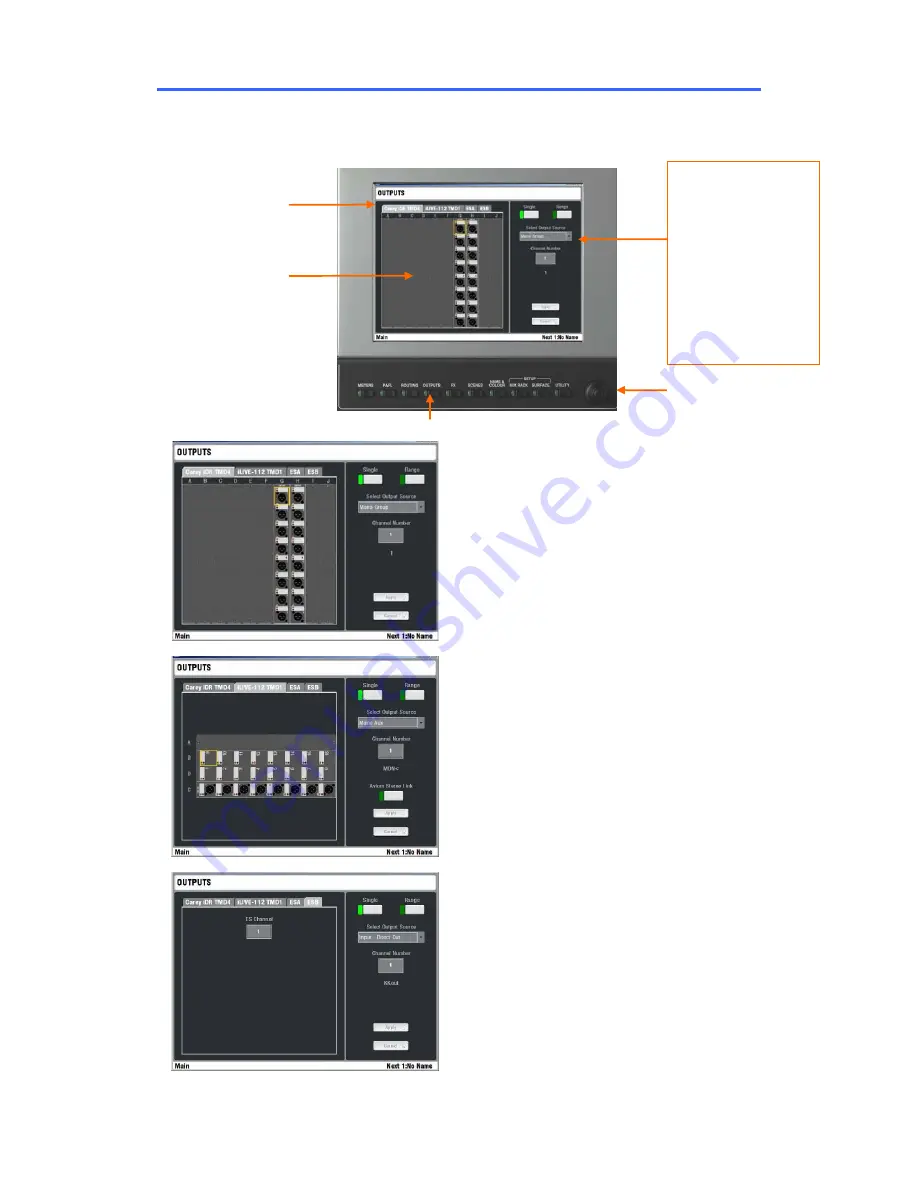
Patching the Outputs
Press the
OUTPUTS
key below the TouchScreen to access the output routing patch bays. These virtual
patch panels display the physical and digital audio network output sockets recognised by the system and
let you route any signal to any output.
MixRack
The tab displays the user name
assigned to the MixRack. The system identifies the
output modules currently loaded (iLive) or fixed
sockets available (T Series) and displays a physical
socket view. Touch a socket to view its current
assignment. Choose a source from the drop down
menu, highlight the Channel Number box and use
the encoder to scroll through the channel numbers.
Touch Apply to confirm.
Work with a
Single
or a
Range
of sockets. For a
range, touch the first then the last. Enter the
Source type, Start and End channel numbers.
Touch Apply to confirm.
Surface
The tab displays the user name
assigned to the Surface. The system identifies the
output modules currently loaded (iLive) or fixed
sockets available (T Series) to the Surface. Assign
as described above.
Port A
This tab is available if the iLive EtherSound
ESA network option is fitted. You can assign
outputs to ESA channels 33 to 62. Channels 1 to
32 are reserved to transport audio from the MixRack
to the Surface audio module slots A to D. Channels
63, 64 transport the PAFL monitor signal from the
MixRack to the Surface.
Port B
This tab is available if a network option
card is fitted to Port B. EtherSound or ACE may be
fitted. You can assign outputs to Port B channels 1
to 64.
OUTPUTS
Tabs to select patch
bay
Touch the socket or
scroll through the
available network
channels
Choose the signal to
send to the socket.:
Not Patched
Mono or stereo Mix
Mix Bus Out
Input Direct Out
MixRack Input
Port A/B source
PAFL monitor
Wedge monitor
IEM monitor
Use the screen
encoder to scroll
through the channels.


