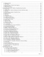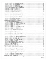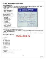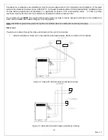
8
Rev 2.1
1 Introduction
This manual covers installation, maintenance, and operation instructions as well as instruction manuals for each of the
control options. Please review this manual carefully before installation or operation. A copy of this manual should be kept
with the boiler at all times for reference. If this manual is misplaced or lost, check the Ajax Boiler Inc. website,
www.ajaxboiler.com
, to print from an electronic copy or contact your local Ajax Boiler Inc representative.
Atlas Series High Efficiency Condensing Boilers have a rugged all-steel frame and low jacket temperatures allowing zero-
clearance installation on combustible flooring. It features 6½" forklift holes for easy handing, a front removable exchanger
assembly for serviceability, an efficient blower allowing at least 30 ft each of intake and exhaust vertical venting, and a
microprocessor based flame safeguard with non-volatile ignition lockout.
The heat exchanger tubes are formed into a cylindrical shape to provide maximum waterside and fireside performance.
The entire heat exchanger assembly is easily removable and replaceable using hand tools only, without performing
welding or cutting operations and without the use of gaskets. Your condensing boiler is E.T.L. listed and carries the E.T.L.
listing mark. It is constructed and stamped in accordance with Section IV of the ASME Code, and is stamped on the
nameplate with applicable markings.
Warning:
Improper installation, adjustment, alteration, service or maintenance can cause property damage, personal
injury, loss of warranty, exposure to hazardous materials or loss of life. Review the information in this manual carefully.
For your safety:
Do not store or use gasoline or other flammable vapors and liquids or other combustible materials in the
vicinity of this or any other appliances. To do so may result in an explosion or fire.
What to do if you smell gas:
•
Do not try to light any appliance
•
Open any windows and secure area
•
Do not touch any electrical switch; do not use any phone in your building.
•
Immediately call your gas supplier from a neighbor’s phone. Follow the gas supplier’s instructions.
•
If you cannot reach your gas supplier, call the fire department.
Installation and Service must be performed by a qualified installer, service agency or the gas supplier
Warning:
Make sure the gas on which the boiler will operate is the same as that specified on the boiler rating plate
(natural gas/propane).
Warning:
Caution when servicing gas train components. Propane (LPG) is heavier than air and may trap in pipes, vents,
combustion chamber, or other areas. Always handle with care.
Warning:
Should overheating occur or if the gas supply valve fails to shut, do not turn off or disconnect the electrical
supply to the boiler. Instead, shut off the gas supply at a location external to the boiler.
Warning:
Do not use this boiler if any part has been under water. Immediately call a qualified service technician to inspect
the boiler and to replace any part of the control system or any gas control which has been under water.
Warning:
To minimize the possibility of improper operation, serious injury, fire, or damage to the boiler:
1. Always keep area around the unit(s) free of chlorine, combustible materials, gasoline, and other flammable liquids and
vapors.
2. Water to be heated in the boiler should be free or have low levels of chlorine or other chemicals or water conditions that
would be harmful to the copper heat exchanger. Boiler room ambient temperature shall not exceed 100 degrees F.
3. Boiler should never be covered or have any blockage to the flow of fresh air to the boiler.
Warning:
Risk of electrical shock. More than one disconnect switch may be required to de–energize the equipment
before servicing.
Warning:
When servicing ceramic fiber based refractory or insulation blanket, gloves and respirators should be worn to
reduce exposure to airborne Refractory Ceramic Fibers.
Содержание A050-A300
Страница 21: ...21 Rev 2 1 Figure 2 4 Suggested Single Fuel Atlas Gas Piping Figure 2 5 Suggested Dual Fuel Atlas Gas Piping ...
Страница 28: ...28 Rev 2 1 ...
Страница 31: ...31 Rev 2 1 Figure 2 10 One Atlas One Tank Suggest Piping Diagram ...
Страница 32: ...32 Rev 2 1 Figure 2 11 One Atlas Two Tank Piping Diagram ...
Страница 33: ...33 Rev 2 1 Figure 2 12 Two Atlas One Tank Piping Diagram ...
Страница 34: ...34 Rev 2 1 Figure 2 13 Two Atlas Two Tank Piping Diagram ...
Страница 36: ...36 Rev 2 1 Figure 2 15 Two Atlas in Primary Secondary Loop Piping Diagram ...
Страница 113: ...113 Rev 2 1 ...


