37
Rev 2.1
3 Basic Panel Operating Procedures
3-1 Introduction
The information in this Chapter provides a guide to the operation of the boiler using the
Basic Panel
mounted on the front
of the unit. It is imperative that the initial startup of this unit be performed by factory trained personnel.
Operation prior to
initial startup by factory trained personnel will void the equipment warranty
. In addition, the following
WARNINGS
and
CAUTIONS
must be observed at all times.
CAUTION:
All of the installation procedures in previous chapters must be completed before attempting to start the unit.
WARNING:
ELECTRICAL VOLTAGES IN THIS SYSTEM MAY INCLUDE 120 AND 24 VOLTS AC. IT MUST BE
SERVICED ONLY BY FACTORY CERTIFIED SERVICE TECHNICIANS
WARNING:
DO NOT ATTEMPT TO DRY FIRE THE BOILER. MAKE SURE PROPER WATER FLOW IS SUPPLIED TO
THE COIL. STARTING THE UNIT WITHOUT WATER CIRCULATION CAN SERIOUSLY DAMAGE THE UNIT AND MAY
RESULT IN INJURY TO PERSONNEL OR PROPERTY DAMAGE.
THIS SITUATION WILL VOID ANY WARRANTY
.
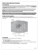
3-2 Basic Panel Description
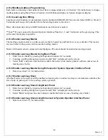
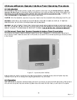
The Basic panel shown in
Figure 3.1
contains all of the controls, indications necessary to operate, adjust and
troubleshoot the boiler. Additional information on these items is provided in the individual operating procedures provided
in this Chapter.
Figure 3.1 – Basic Panel Front View
3-3 Operation
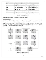
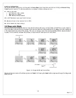
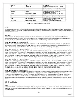
All data from the Basic Panel is displayed on an LCD with backlight.
The LCD has two main zones:
•
Numerical
Display
contains numbers (Temperatures in degrees, firing rate in percentages).
•
Operating Mode Icons
indicate what mode the Unit is in.
The Basic Panel includes four keys. The bottom two keys vary depending on what commands are displayed above them.
The two keys on the right adjust the displayed information.
Three operation modes are available:
User Mode
,
Setup Mode
, and
Diagnostic Mode
.
Содержание A050-A300
Страница 21: ...21 Rev 2 1 Figure 2 4 Suggested Single Fuel Atlas Gas Piping Figure 2 5 Suggested Dual Fuel Atlas Gas Piping ...
Страница 28: ...28 Rev 2 1 ...
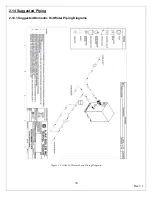
Страница 31: ...31 Rev 2 1 Figure 2 10 One Atlas One Tank Suggest Piping Diagram ...
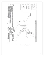
Страница 32: ...32 Rev 2 1 Figure 2 11 One Atlas Two Tank Piping Diagram ...
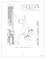
Страница 33: ...33 Rev 2 1 Figure 2 12 Two Atlas One Tank Piping Diagram ...
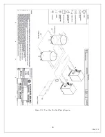
Страница 34: ...34 Rev 2 1 Figure 2 13 Two Atlas Two Tank Piping Diagram ...
Страница 36: ...36 Rev 2 1 Figure 2 15 Two Atlas in Primary Secondary Loop Piping Diagram ...
Страница 113: ...113 Rev 2 1 ...

