13
Rev 2.1
2 Installation
2-1 Installation Codes
Installations must follow these codes:
•
Local, state, provincial, and national codes, laws, regulations and ordinances
•
National Fuel Gas Code, ANSI Z223.1/ NFPA 54 – latest edition (NFGC)
•
National Electrical Code, ANSI/ NFPA 70 – latest edition (NEC)
•
Standards for Controls and Safety Devices for Automatically Fired Boilers, ANSI/ASME CSD–1, (CSD–1) when
required.
Note:
If any code listed above conflict, the stricter of the conflicting codes shall be followed
for installation.
Note:
Installation and Service must be performed by a qualified installer, service agency or the
gas supplier
2-2 Equipment Base
The boiler should be mounted on a level, structurally sound surface. The boiler is approved for mounting on a combustible
surface but cannot be installed on carpeting. Gas fueled equipment installed in enclosed parking garages must be located
at least 18" above the floor.
Note:
Ajax strongly recommends that you secure the boiler to the base pad by the mounting holes provided at the base of
the unit.
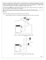
Figure 2.1. Isometric View of Atlas Base with Mounting Holes
Caution:
Locate the unit so that the condensate can be treated and piped to meet city and local code requirements.
The boiler shall be installed such that the gas ignition system components are protected from water (dripping, spraying,
rain, etc.) during boiler operation or service (circulator replacement, control replacement, etc.)
2-3 Determining Unit Location
The optimal location for the boiler is as close to an exterior wall as possible to reduce vent loss and to minimize the costly
exhaust Stainless Steel vent materials. Maintain minimum specified clearances for adequate operation. All installations
Содержание A050-A300
Страница 21: ...21 Rev 2 1 Figure 2 4 Suggested Single Fuel Atlas Gas Piping Figure 2 5 Suggested Dual Fuel Atlas Gas Piping ...
Страница 28: ...28 Rev 2 1 ...
Страница 31: ...31 Rev 2 1 Figure 2 10 One Atlas One Tank Suggest Piping Diagram ...
Страница 32: ...32 Rev 2 1 Figure 2 11 One Atlas Two Tank Piping Diagram ...
Страница 33: ...33 Rev 2 1 Figure 2 12 Two Atlas One Tank Piping Diagram ...
Страница 34: ...34 Rev 2 1 Figure 2 13 Two Atlas Two Tank Piping Diagram ...
Страница 36: ...36 Rev 2 1 Figure 2 15 Two Atlas in Primary Secondary Loop Piping Diagram ...
Страница 113: ...113 Rev 2 1 ...


