background image


aj-aircraft.com


Page 1 


Up Your Game! Fly AJ Aircraft 

AJ Aircraft thanks you for the purchase of this airplane. Top grade materials and precision assembly have been 
used to make this a top quality aircraft.  Following the directions closely, will assure you many hours of 
thrilling flight.  Two years of design, development and testing has gone into this airframe.  We hope you’re as 
happy with it as we are! 

WARNING

AJ Aircraft’s extensive testing ensures a high quality kit that has gone through many stages to provide you with 
a safe, reliable, airframe.  Poor assembly will lead to an unsafe model and therefore the instructions must be 
followed closely.  Should you have any questions, please do not hesitate to contact us.  The safe operation of 
this model is your responsibility and yours alone.  If you are a beginner or have never flown a model of this 
size and power you should attempt it with the help of an experienced pilot.  This product should not be 
considered a toy, but rather a sophisticated, working model that functions much like a full-scale airplane.  
Because of its performance capabilities, this product, if not assembled and operated correctly, could cause 
injury to you or spectators and damage to property. 

This aircraft should be flown in accordance to th

AMA safety code

 It is highly recommended that 

you join the Academy of Model Aeronautics in order to be properly insured and to operate your model at 
AMA sanctioned flying fields.  If you are not willing to accept all liability for the use of this product please 
return if to the place of purchase immediately. 

AJ Aircraft does not accept responsibility or liability for damages resulting from use of this product.   

Before starting, read through the entire set of instructions to familiarize yourself with the 
process. 

Additional assembly information can be found in assembly videos on the 

AJ-Aircraft YouTube Channel


If there’s ever a question, contact AJ Aircraft. 734-244-4015 


Содержание 2M AJ Acuity

Страница 1: ...2M AJ Acuity Assembly Instructions ...

Страница 2: ...ould attempt it with the help of an experienced pilot This product should not be considered a toy but rather a sophisticated working model that functions much like a full scale airplane Because of its performance capabilities this product if not assembled and operated correctly could cause injury to you or spectators and damage to property This aircraft should be flown in accordance to the AMA saf...

Страница 3: ...gram batteries 10 5 lbs Electric Power 2500 3000 Watt Motor 90amp ESC 2x 5s 5000mah LiPo Radio 6 Channel receiver 2 Mini 15x33x27 size Servos Elevator 3 Standard 20x40x34 size Servos Ailerons Rudder What s in the box 2M Acuity Airframe Fiberglass Cowl Wheel Pants Carbon reinforced landing gear mount Pre hinged control surfaces not glues Removable rudder and stabilizers Carbon main gear and tail wh...

Страница 4: ...r Futaba BLS173 servos on Elevator 4 x 6 Servo Extensions for the Ailerons and Rx to Wing 1 x 12 Servo Extension for the ESC to Receiver 2 x 48 Servo Extension for the Elevator 7 Servo Connector Safety Clips 3 25 or 82mm Spinner Tools Needed Blue Painter s Masking Tape Thin CA Glue 30 Minute Epoxy Denatured Alcohol Paper Towels Removable Thread Locker Loctite 242 Blue Metric Imperial Allen Wrenche...

Страница 5: ...70 Midnight Blue HANU885 Cub Yellow HANU884 Black HANU874 Competition Blue True Red HANU866 White HANU870 Midnight Blue HANU885 Cub Yellow HANU884 Black HANU874 At 200 220 F 93 104 C the adhesive on UltraCote becomes active allowing the covering to be attached to the model While 220 will fully bond the covering to the model it is well below the temperature that causes UltraCote to shrink At 300 F ...

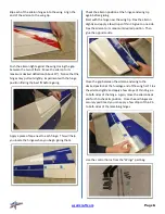
Страница 6: ...eting and attach it to the inside edge of the pocket Carefully locate the aileron control horn slots About 4 15 16 125mm from the edge of the aileron Use a covering iron to bond the covering in the area the control horn will sit Trim the covering away to expose the slots Be sure not to cut through to the top side covering The hinges should already be glued into the ailerons Give each of them a lit...

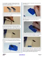
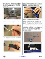
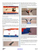
Страница 7: ... the aileron position at the hinges and wing tip again before gluing Start with the hinge near the wing tip Flex the aileron slightly and apply a few drops of thin CA glue to one side Flex the aileron to its maximum desired position Then glue the opposite side Close the gap between the aileron and wing to the desired position at the fuselage end of the wing half Flex the aileron slightly and apply...

Страница 8: ...rol horn in position apply masking tape around it This will help keep excess epoxy off the wing covering Apply epoxy to the slot in the aileron Use a pin to help push the epoxy in Apply epoxy to the control horn and insert it into the slot Wipe away excess epoxy using a paper towel and denatured alcohol Check the alignment along the hinge line as you did when you test fit the control horn Repositi...

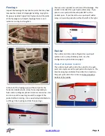
Страница 9: ...ular to the side of the servo Attach a servo extension and a safety clip to the servo Attach the servo wire to the installation string and gently pull the wire through the wing as you insert the servo into the wing Reinstall the servo Thread 2 ball links onto a turnbuckle connecting rod Notice that one end of the rod has a right hand thread and the other end has a left hand thread Adjust the lengt...

Страница 10: ...r Landing gear parts bag contents are shown below The landing gear screws are supplied installed in the fuselage Remove the 6 M4 socket head screws Carefully locate the landing gear slot in the side of the fuselage just below the leading edge of the wing location Make a cut in the center of the slot and at the corners Use your trim iron to fold and attach the covering into the slot Slip the landin...

Страница 11: ...en into landing gear Align the wheel pant indentation with the landing gear Add a nylon lock nut and tighten Install the tail wheel after the rudder installation Install the tailwheel using 3 wood screws Position the joint of the tail wheel assembly directly over the rudder hinge line and mark the position of the screws Turn the screws into the fuselage and rudder Remove the screws add a drop of t...

Страница 12: ...ife blade to cut though the covering and trim the openings There is a servo pocket on each side of the fuselage This pocket is intended for a push pull rudder setup If you plan to use a pull pull cable setup DO NOT cut the pockets open If you intend to use a push pull rudder setup cut open the pocket on either the left or the right Rudder The rudder control can be configured as a push pull system ...

Страница 13: ...orn slot on both sides of the rudder Use sandpaper to roughen up the end of the control horn so the epoxy will adhere better Tests fit the control horns to the slots Use a file to modify the slot as needed The control horn should be symmetrical about the hinge line A strait edge laid across the control horn cable holes should be square to the rudder centerline Apply masking tape around the control...

Страница 14: ... snap Drill a larger pilot hole if needed Apply a drop of thin CA glue into each mounting screw hole This will harden the wood around the screws and provide a more secure installation Allow the CA glue to dry before reinstalling the servo Tread the brass cable eyes about half way into the ball links Start the cable assembly at the servo end inside the fuselage Thread on 2 crush sleeves and the bra...

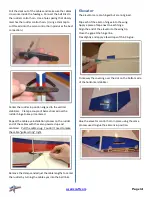
Страница 15: ...dder end of the cables with the servo powered up and centered Pull the cable snug You don t need to make the cable guitar string tight Remove the clamps and adjust the cable lengths to center the rudder by turning the cable eyes into the ball links Elevator The elevators are pre hinged but are not glued Slip each of the aileron hinges into the wing Apply a piece of tape next to each hinge Align th...

Страница 16: ...tal stabilizer is typically easier Fold the servo wire towards the top of the servo Rotate the servo control horn to fit into the horizontal stabilizer Tip the servo so the wired end goes in first Thread 2 ball links onto a turnbuckle connecting rod Notice that one end of the rod has a right hand thread and the other end has a left hand thread Evenly centering the rod between the ball links Connec...

Страница 17: ...wever you will need to use the 5mm shaft spacer that comes with the motor Bolt the motor directly to the firewall using 4mm socket head cap screws and flat washers Apply a drop of removable thread locker when installing the motor screws If you are using another motor you may need to use motor standoffs The cowl length is 3 7 16 87mm from the firewall which will help you plan your motor spacing Use...

Страница 18: ...ole on the tape Peal the tape back away from each hole but leave it attached to the fuselage Place the cowl canopy and spinner back plate in position Center the cowl around the spinner back plate leaving a clearance gap Position the cowl with the fuselage and the canopy Securely tape the cowl in position when you ve found the best possible fit Drill a 1 16 hole in the side of the cowl at the locat...

Страница 19: ... attach it using a covering iron Secure the canopy in position with 3mm socket head cap screws and flat washers Slide the T Canaliser through the canopy Measuring from both sides center the T Canaliser in the canopy Measure from the horizontal stabilizer on both side and adjust as needed to ensure that it is parallel with the horizontal stabilizer Tape the T Canaliser in position when you have fou...

Страница 20: ...en any vibration Use the suggested throws below as your starting point then fine tune to your flying preferences after your first few flights Take the time to properly balance and trim your aircraft The center of gravity range is located from the back edge of the carbon fiber fuselage support to 10mm back To test the CG fly left or right at about 3 4 to full throttle and pull to a 45 degree up lin...

Страница 21: ... to create a support ticket at aj aircraft com if you have any problems questions or suggestions Once you get a few flights in we would greatly appreciate your review submitted to our web site See you at the field AJ Aircraft 2410 N Monroe St Monroe MI 48162 USA Phone 734 244 4015 Manual 1 03 20 Andrew with the 62 Acuity ...

Отзывы: