Page 11
Fuselage
Inspect the fuselage for any interior joints that may have
loosened as a result of shipping & handling. Apply thin
CA glue as needed. Apply thin CA glue around the joints
of the fuselage core, firewall, fuselage formers, and
rudder servo tray to strengthen.
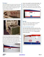
At the tail of the fuselage you will find a hole for the
horizontal stabilizer tube, screw holes, alignment pin
holes and a rectangular pocket to access servo wires. Use
an iron to seal the covering around the edges of the
pocket before trimming. Use a new hobby knife blade to
cut though the covering and trim the openings.
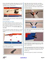
There is a servo pocket on each side of the fuselage. This
pocket is intended for a push pull rudder setup. If you
plan to use a pull-pull cable setup DO NOT cut the
pockets open. If you intend to use a push-pull rudder
setup cut open the pocket on either the left or the right.
Rudder
The rudder control can be configured as a push-pull
system or as a pull-pull cable system. See the
configuration options listed on page 3.
Push-Pull Rudder Control
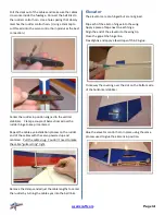
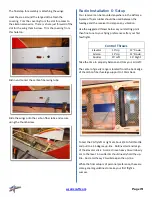
The rudder is built with control horn slots for the push-
pull control system and the pull-pull control system. The
blue masking tape indicates the control horn locations.
The push-pull control horn slots are located near the
bottom of the rudder.
Содержание 2M AJ Acuity
Страница 1: ...2M AJ Acuity Assembly Instructions ...

