14
Gen IV Controller with Smart Arm Setup Instruction Manual
11. Icon Reference
Icon
Function
Definition
Position not
valid
The current position of the arm does not
match any locations in the smart arm
configuration. This error will clear when
the arm is in a valid position.
‘SARM’ will show on the top LED display.
Location
Complete
This will appear when Jobs are enabled
and the current location has already
had an OK fastening.
Only appears when the custom
runscreen image is configured.
‘SARM’ will show on the top LED display.
PSet or Job
Sequence
Mismatch
The currently selected PSet or Job
Sequence does not match the PSet
or Job Sequence number required by
the current location. This error will clear
when one of the following happens:
• The arm moves to a position that
requires the currently selected PSet/
Sequence
• The active PSet/Sequence is
changed to match what is required
for this position
‘PSET’ or ‘JSEQ’ will show on the top LED
display.
Connection
Error
The controller is not communicating with
the accessory. Commonly caused by
incorrect IP settings in the controller or
accessory.
‘SARM’ will show on the top LED display.
12. References
• 30887 – Smart Arm Assembly
• Encoder - Kubler 8.3620.525E.2048
• 30860 - Smart Arm Accessory – Encoder Interface
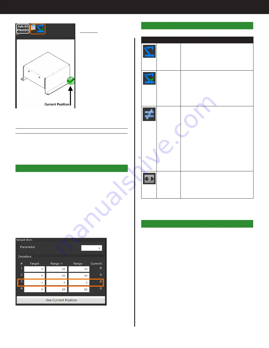
Image 8
All fasteners inserted.
Tool is disabled.
Status bar shows job
complete. Reset job
to start new part.
For a description of icons, see "Icon Reference" on
9.2.6 Clearing locations
The ‘Reset Job’ input will always clear the Smart Arm
Runscreen. Any positions marked as complete will
be reset.
10. Adding a Proximity or Limit Switch
A proximity switch or limit switch can be wired in
to one of the encoder inputs. This will allow one
of the encoder readings to read as 0/1 or 0/-1
depending on how the switch is wired. The switch
will always read one of two states so the range
for that encoder will need to be set to 0. For the
configuration in the image below the 3rd encoder
is set to work with a proximity switch. The location
is only valid when the encoder is reading a -1. The
range is 0 so that the target has to be an exact
match.
Use the pinouts in “Hardware Connections” to wire
in the proximity switch to an M12-8 connector. Use
0V (pin 1) and 12V (pin 2) to power the switch and
connect the signal wire to the ‘A’ input (pin 3)
Содержание AcraDyne
Страница 15: ......


