9
Gen IV Controller with Smart Arm Setup Instruction Manual
▪
Controller IP Address: 192.168.100.1
▪
Subnet: 255.255.255.0
• Set up the accessory ethernet settings
○
Go to the Accessory screen and click the
gear icon
○
The accessory attached to the second
ethernet port will appear in the list
○
Verify the MAC address shown matches the
MAC printed on the accessory box.
○
Click on the accessory in the list and the edit
fields below will autofill
○
Configure the accessory to have the
following settings:
▪
IP Address: 192.168.100.5
▪
Subnet: 255.255.255.0
▪
Gateway: 0.0.0.0
○
Click ‘Send’
○
The accessory list will refresh and the
accessory will show with its new settings.
• Add the smart arm accessory
○
Navigate to the main accessory screen and
click Add(+)
○
Enter the IP address that was just configured
for the accessory
▪
IP Address: 192.168.100.5
○
Click OK/Check
• Verify connection
○
Runscreen status header
▪
The main runscreen will now show an
arm icon indicating that it is not in a
valid location
○
Live encoder values
▪
Navigate to Accessories and edit the
smart arm accessory
▪
Click the Add(+) button to add a new
location. The fields under ‘Current’
should change as the arm is moved.
This shows that the accessory is sending
over valid encoder values.
9.1 Example 1: Select PSets Based on Location
This example shows how to set up the most basic
control option. Three locations will be programmed
in the controller so that the controller will enable
the tool and select a specific PSet when the tool is
located over a fastener.
9.1.1 PSet Setup
Create three PSets. These can be named in the
advanced settings to make it more clear which PSet
is for which bolt.
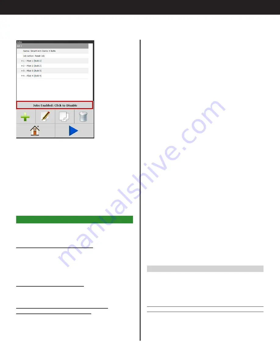
The Jobs screen gives the option to Enable or
Disable jobs. Click to toggle between the two.
•
Jobs Enabled
Smart arm configuration will be automatically
updated to the part image ID chosen through
this jobs interface.
•
Jobs Disabled
Smart arm configuration will be updated to the
image uploaded through the main smart arm
interface. See "8.1 Add, Edit, or Delete Custom
9. Examples
For the examples given below, set up the controller
and smart arm as follows.
Smart Arm Accessory Connections
• 4x Encoder Connections – M12
▪
Connect each encoder to an encoder
connector starting at encoder 1
• 1x Remote Home Button Connection – M8
• Ethernet
Gen IV Controller Connections
• Use second ethernet port to connect to
accessory
Initial Setup: Configuring the Controller to
Communicate with the Accessory
•
Configure the second ethernet port on the
controller
○
This example is set up to work with the default
IP settings on the second ethernet port of the
controller
Содержание AcraDyne
Страница 15: ......


