USE OM - JANUARY 2017
58
5.2.3.5
At least one (1) thermocouple shall be attached via solder method per ASHRAE
Standard 41.1 Section 7.2.10; or mechanically attach thermocouples to each potential large thermal
mass between the outlet of the UUT and the grid of thermocouples specified in Section 5.2.3.4.
Thermocouples shall be connected in parallel.
5.2.4
Running the Test Procedure.
5.2.4.1
The indoor blower motor shall be left unpowered throughout this Thermal Energy
Storage Effect Test.
5.2.4.2
Indoor air inlet conditions shall be maintained at 70.0 ±0.5ºF dry-bulb temperature and
65.0 ±0.3ºF wet-bulb temperature.
5.2.4.2.1
The Test Operating Tolerance for dry-bulb temperature shall not exceed
0.5ºF and for wet-bulb temperature shall not exceed 0.3ºF during the test.
5.2.4.3
The airflow shall be set to 1200 SCFM and will run continuously throughout the test.
The heater will be powered to produce between 8 and 10 kW. The heater will be cycled
“on” for 6
minutes then
“off” for 6 minutes. Ten “on”/”off” cycles (2 hours) shall constitute a complete test.
5.2.4.4
Care must be taken to assure the voltage to the heater remains constant at the level
of the test described in Section 5.2.4.3. It is highly recommended that the active variac voltage control
be disabled during the cyclic part of this test.
5.2.4.5
The thermocouple or thermocouples attached to the largest thermal mass in the test
facility, out of line of sight of the heater, shall be recorded on a minimum of ten-second intervals for the
duration of the six-minute
“on” time. Note that if more than one (1) large thermal mass is expected,
then the temperature shall be monitored on each expected large thermal mass and proceed with
calculations based on the experimentally determined largest thermal mass.
5.2.5
Data to Collect
.
5.2.5.1
The following data is the minimum to be collected for Thermal Energy Storage Effect
testing:
All of the data from Section 5.1.5 and the following additional data:
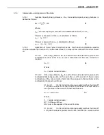
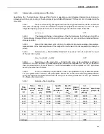
t
m
=
thermal mass, °F
t
m
(0) =
temperature of largest thermal mass between the UUT and the
measurement grid (likely the mixer) at the start of the
“off” cycle, °F
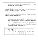
t
m
(
Θ
I
)
= temperature of largest thermal mass between the UUT and the
measurement grid (likely the mixer) at end of the integration time within the
“off” cycle, °F
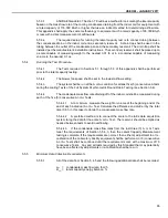
q
cyc,h
= integrated capacity based on the measured watts of the heater, Btu/h
q
cyc,hoff
= integrated capacity based on the measured kW of the
heater during an off cycle, Btu/h
q
ts
= cyclic thermal storage capacity correction, Btu/h
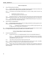
mc
pm
= mass times the specific heat of the thermal storage device per ASHRAE
Standard 116 Section 9.2.2, Btu/°F
Содержание OM 210
Страница 8: ......
Страница 37: ...USE OM JANUARY 2017 29 Figure C2 Use of Unqualified Outdoor Units for ICM Testing ...
Страница 50: ...USE OM JANUARY 2017 42 Figure G2 Part 2 of the ORNL Flowchart ...
Страница 55: ...USE OM JANUARY 2017 47 Figure K1 Nozzle Combination Tests 66 Figure K2 Passive Pressure Drop Device 75 ...


