USE OM - JANUARY 2017
52
5.1.4.2.1
Prior to running any electric heat tests, it is necessary to verify that the
entering and leaving RTD match when no load exists. Select an air flow between 1000
to 1400 range and allow the unit and facility to pre-condition for at least one (1)
hour. Run a test for 30 minutes using normal sample rates. Average the entering and
leaving RTD temperatures and calculate the difference in the averages. If the
difference exceeds 0.03 degrees then calibration of the facility RTDs or test setup
investigation is required. An error at the upper end of this tolerance will result in heat
balance errors of up to ¼ percent.
5.1.4.2.2
Over the various air flow rates to be tested, the voltage to the electric heat
shall be varied in order to maintain a nominal 12 ° F differential temperature across
the indoor unit. Power to the heater shall be set within the range of 3.8 kW to 4.0 kW
per 1000 SCFM measured.
5.1.4.2.3
For each potential nozzle combination at least three (3) air flow rates shall
be tested, as described in Table K1. For the purpose of this Section 5.1, “test” shall
be construed to be a single air flow rate for a given nozzle combination.
5.1.4.3
Test data for each air flow rate shall be recorded at equal intervals, with a maximum
interval period of one (1) minute, over a 30 minute period. Upon completion of the Test, test data shall
be averaged. For each air flow rate Test, there shall be a minimum 30 minute Pre-conditioning Test.
5.1.4.4
For sensible heat balance calibration, the blower shall not be powered and the UUT
shall have all joints and seams taped or sealed (internally and externally as required) for all tests to
eliminate air from leaking past the heater.
5.1.4.5
For each potential nozzle combination, at least one (1) Test of a previously run air flow
rate shall be retested with the blower energized.
5.1.4.6
For each potential nozzle combination, at least one (1) Test of a previously run air flow
rate shall be retested with one (1) bank of electric heaters turned off and one (1) bank on.
Содержание OM 210
Страница 8: ......
Страница 37: ...USE OM JANUARY 2017 29 Figure C2 Use of Unqualified Outdoor Units for ICM Testing ...
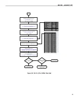
Страница 50: ...USE OM JANUARY 2017 42 Figure G2 Part 2 of the ORNL Flowchart ...
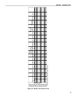
Страница 55: ...USE OM JANUARY 2017 47 Figure K1 Nozzle Combination Tests 66 Figure K2 Passive Pressure Drop Device 75 ...


