


15
IDP-7 Dry Scroll Vacuum Pump
DRAF
T 1/19/17
Mechanical Connections
Isolation Valve
The IDP-7 has an optional integral automatic isolation
valve. If the IDP-7 is equipped with this valve, an internal
timer opens the valve 30 seconds after the pump is
switched ON. If power is lost or the pump is switched
OFF, the isolation valve will immediately close.
Pump Inlet
Use NW25, or larger, clean vacuum hardware with as
short a length as practical between the pump and vacuum
chamber.
Insert a bellows between the pump and vacuum chamber
to provide both vibration isolation and strain relief.
Pump Exhaust
An NW16 exhaust fitting is located radially near the front
of the pump. To avoid overheating the pump, do not
restrict the exhaust flow with long lengths of small diame-
ter tubing. Use as short as practical lengths of NW16, or
larger, diameter hardware.
Gas Ballast
When pumping gas loads containing water vapor or con-
densible gases, use of the gas ballast is recommended. To
activate gas ballast, remove the solid 1/4 NPT plug from
either port 1 or port 2 (may be removed using a 9/16" nut
driver), and install the sintered filter plug provided with
the pump (see Figure 3 on page 11).
Gas ballast port 1 is used for moderate water vapor loads,
such as intermittently pumping out a volume exposed to
normal ambient humidity. Gas ballast port 2 is used for
high water vapor loads, such as repetitively pumping out
a volume exposed to excessive ambient humidity, or pro-
cess gas loads with a high water vapor content. With both
gas ballast 1 and gas ballast 2 in use, up to 120 g/hr water
vapor can be handled. If both gas ballast 1 and gas ballast
2 are open (plugs removed, allowing for air flow), the sin-
tered filter plug should be installed in the gas ballast 2
location instead of the gas ballast 1 location.
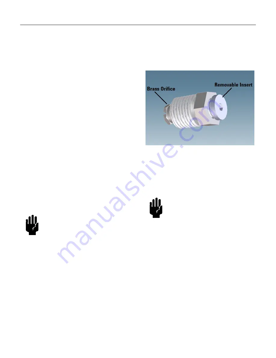
If either gas ballast is to be used for only short intervals,
the removable insert may be taken out of the gas ballast
without removing the entire plug. By removing this insert
(may be removed using a 1/8" hex wrench), the gas bal-
last allows for air flow through the brass orifice. There is
no need to remove the brass orifice.
Figure 5 Gas Ballast
Gas ballast plug assembly in both port 1 and port 2.
For applications where ingress of air is undesirable, dry
nitrogen at a flow rate of approximately 5 l/min can be
provided to the gas ballast inlet by making a 1/4 NPT
connection to the port.
CAUTION
If hazardous materials are pumped, do
not use gas ballast.
CAUTION
Pumping high water vapor loads can
cause a temporary increase in ultimate
pressure, due to adsorption and absorp-
tion of water vapor by the internal sur-
faces of the pump. Pumping water
vapor loads in excess of the water vapor
handling capability of the gas ballast
can cause reduced time between tip
seal replacements.


