background image

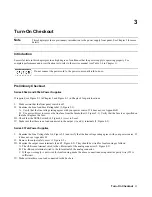
   Turn-On Checkout

32

POWER-ON Checkout

1.


Connect the power cord to the power source.

2.


Turn the front panel power switch to ON (1).

3.


Check that the power supply fan is on by placing your hand near the rear grill to feel the  air flow. You may also be able
to hear the fan operating.

The power supply undergoes a self-test when you turn it on. If the test is normal, the  following sequence appears on the
LCD:

1.


A brief star-burst pattern   

2.


PWR 0N INIT for a few seconds (Series 657xA supplies only).

3.


The display goes into the meter mode with the 

Dis

 annunciator on and all others off.  “Meter mode” means that the

VOLTS

 digits indicate the output voltage and the 

AMPS

 digits indicate the output current. These values will be at or

near zero.


Note

If the power supply detects an error during self-test, the display will show an error message. Go to “In


Case of Trouble” at the end of this chapter.


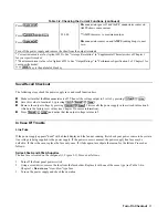
4.


Press 

 once. The 

Dis

 annunciator will go off and the 

CV

 annunciator will go on.

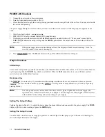
Output Checkout

Shifted Keys

Some of the front panel keys perform two functions, one labeled in black and the other in blue. You access the blue function
by first pressing the blue 

 key, which is not labeled. When the 

Shift

 annunciator is on, you will know you have

access to the key's shifted (blue) function.

Backspace Key

The

key is an erase key. If you make a mistake entering a number and have not yet entered it (have not pressed

),  you can delete the number by pressing 

. You may delete as many numbers as you wish by repeatedly

pressing this key.

Note

The voltage and current values used in these tests are for a typical Agilent 655xA Series supply (the
Agilent 6552A). Table 1-la and Table 1-lb in Chapter 1 lists the ranges for other supplies. If needed, refer
to those tables for the voltage and current ratings of your supply.

Setting The Output Voltage

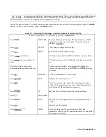
Perform the steps in Table 3-1 to check the basic voltage functions with no load connected to the power supply. The 

VOLTS

display will show various readings. Ignore the 

AMPS

 display.

Setting The Output Current

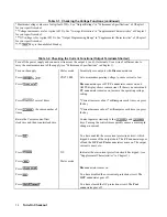
You must have a load on the power supply to generate a current output. For this purpose, you will connect a shorting wire
across the output terminals of the supply.

Содержание 654xA Series

Страница 1: ...OPERATING MANUAL Analog Programmable DC POWER SUPPLIES Agilent Technologies Series 654xA 655xA 657xA sA Agilent Part No 5959 3374 Printed in Malaysia Microfiche Part No 5959 3375 July 2004 ...

Страница 2: ...rned to Customer from another country Agilent Technologies shall pay for return of products to Customer Warranty services outside the country of initial purchase are included in Agilent Technologies product price only if Customer pays Agilent Technologies international prices defined as destination local currency price or U S or Geneva Export price If Agilent Technologies is unable within a reason...

Страница 3: ...d current voltage and specified type normal blow time delay etc should be used Do not use repaired fuses or short circuited fuseholders To do so could cause a shock or fire hazard DO NOT OPERATE IN AN EXPLOSIVE ATMOSPHERE Do not operate the instrument in the presence of flammable gases or fumes KEEP AWAY FROM LIVE CIRCUITS Operating personnel must not remove instrument covers Component replacement...

Страница 4: ...tsplatz Normaler Betrieb Nach EN 27779 Typprufung Manufacturer s Declaration This statement is provided to comply with the requirements of the German Sound Emission Directive from 18 January 1991 Sound Pressure Lp 70 dB A At Operator Position Normal Operation According to EN 27779 Type Test Printing History The edition and current revision of this manual are indicated below Reprints of this manual...

Страница 5: ...the Low Voltage Directive 73 23 EEC and the EMC Directive 89 336 EEC including 93 68 EEC and carries the CE Marking accordingly EMC Information ISM Group 1 Class A Emissions As detailed in Electromagnetic Compatibility EMC Certificate of Conformance Number CC TCF 02 020 based on Technical Construction File TCF HPNJ2 dated June 4 2002 Assessed by Celestica Ltd Appointed Competent Body Westfields Ho...

Страница 6: ...ve 89 336 EEC including 93 68 EEC and carries the CE Marking accordingly EMC Information ISM Group 1 Class A Emissions As detailed in Electromagnetic Compatibility EMC Certificate of Conformance Number CC TCF 00 074 based on Technical Construction File TCF HPNJ1 dated Oct 27 1997 Assessed by Celestica Ltd Appointed Competent Body Westfields House West Avenue Kidsgrove Stoke on Trent Straffordshire...

Страница 7: ...nd carries the CE Marking accordingly EMC Information ISM Group 1 Class A Emissions As detailed in Electromagnetic Compatibility EMC Certificate of Conformance Number CC TCF 00 074 based on Technical Construction File TCF HPNJ1 dated Oct 27 1997 Assessed by Celestica Ltd Appointed Competent Body Westfields House West Avenue Kidsgrove Stoke on Trent Straffordshire ST7 1TL United Kingdom Safety Info...

Страница 8: ... 654xA and 655xA Supplies 28 Series 657xA Supplies 28 3 Turn On Checkout Introduction 31 Preliminary Checkout 31 Series 654xA and 655xA Supplies 31 Series 657xA Supplies 31 Power On Checkout 32 Output Checkout 32 Shifted Keys 32 Backspace Key 32 Setting the Output Voltage 32 Setting the Output Current 32 Save Recall Checkout 35 In Case of Trouble 35 Line Fuse 35 Series 654xA and 655xA Supplies 35 ...

Страница 9: ...ions 47 Auto Parallel Operation 47 Auto Parallel Wiring 47 General Auto Parallel 48 Series 654xA and 655XA Auto Parallel Programming 48 Series Operation 49 External Voltage Control 49 Programming Series 654xA and 655xA Supplies 50 Programming Series 657xA Supplies 51 OVP Considerations 51 Remote Sensing 51 Battery Charging 51 Series 654xA and 655xA Load Capacitance 51 5 Front Panel Operation Intro...

Страница 10: ... Performing the Calibration 64 Entering the Calibration Values 64 Saving the Calibration Constants 64 Changing the Calibration Password 64 Disabling the Calibration Mode 66 Calibration Error Messages 66 B Line Voltage Conversion Series 654xA and 655xA Power Supplies 67 Series 657xA Power Supplies 68 Index 69 AGILENT Sales and Support Office 75 ...

Страница 11: ... identified by a unique two part serial number such as 3343A 00177 The first part or prefix is a number letter combination that provides the following information 3343 The year and week of manufacture or last significant design change Add 1960 to the first two digits to determine the year For example 33 1993 34 1994 etc The last two digits specify the week of the year 43 the 43rd week A The letter...

Страница 12: ...lies Analog Family Corresponding GPIB Family Agilent 654xA Agilent 664xA Agilent 655xA Agilent 665xA Agilent 657xA Agilent 667xA Each power supply is programmable locally from the front panel or remotely via a rear panel analog control port Operational features include Constant voltage CV or constant current CC output over the rated output range Built in overvoltage OV overcurrent OC and overtempe...

Страница 13: ...nt is determined by the voltage setting Vs the current setting Is and the load impedance Two operating points are shown Point 1 is defined by the load line cutting the operating locus in the constant voltage region This region defines the CV mode Point 2 is defined by the load line cutting the operating locus in the constant current region This region defines the CC mode Downprogramming The power ...

Страница 14: ...6543A 6553A 6544A 6554A 6545A 6555A 3 mV 3 mV 4 mV 5 mV 7 mV Constant Current rms 6541A 6542A 6543A 6544A 6545A 10 mA 5 mA 3 mA 1 5 mA 1 mA 6551A 6552A 6553A 6554A 6555A 25 mA 10 mA 5 mA 3 mA 2 mA Readback Accuracy with respect to actual output 25 C 5 C Voltage 6541A 6551A 6542A 6552A 6543A 6553A 6544A 6554A 6545A 6555A 0 07 6 mV 0 07 15 mV 0 07 25 mV 0 07 40 mV 0 07 80 mV Current 6541A 6542A 6543...

Страница 15: ... 6554A 6545A 6555A 8 8 V 22 0 V 38 5 V 66 0 V 132 0 V Current 6541A 6542A 6543A 6544A 6545A 20 475 A 10 237 A 6 142 A 3 583 A 1 535 A 6551A 6552A 6553A 6554A 6555A 51 88 A 25 594 A 15 356 A 9 214 A 4 095 A Average Resolution Voltage 6541A 6551A 6542A 6552A 6543A 6553A 6544A 6554A 6545A 6555A 2 mV 5 mV 10 mV 15 mV 30 mV Current 6541A 6542A 6543A 6544A 6545A 6 mA 3 mA 2 mA 1 mA 0 5 mA 6551A 6552A 65...

Страница 16: ...m 0 20mA 95ppm 0 08mA 6551A 6552A 6553A 6554A 6555A 90ppm 1 7mA 90ppm 0 9mA 90ppm 0 5mA 90ppm 0 3mA 90ppm 0 2mA Current Readback 6541A 6542A 6543A 6544A 6545A 110ppm 1 2mA 110ppm 0 62mA 110ppm 0 33mA 110ppm 0 20mA 110ppm 0 08mA 6551A 6552A 6553A 6554A 6555A 100ppm 1 7mA 100ppm 0 9mA 100ppm 0 5mA 100ppm 0 3mA 100ppm 0 2mA Overvoltage Protection 6541A 6551A 6542A 6552A 6543A 6553A 6544A 6554A 6545A ...

Страница 17: ...ges Downprogrammer Current Capability 15 Agilent 6541 Agilent 6542 Agilent 6543 Agilent 6544 Agilent 6545 5 8 A 2 5 A 1 5 A 0 9 A 0 75 A Agilent 6551 Agilent 6552 Agilent 6553 Agilent 6554 Agilent 6555 11 6 A 5 A 3 A 1 8 A 1 5 A Monotonicity Output is monotonic over entire rated voltage current and temperature range Auto Parallel Configuration Up to 3 identical models Analog Programming IP VP Inpu...

Страница 18: ...t Model Number and Parameter Value Dimensions Width Height Depth Series 654xA 425 5 mm 16 75 in 88 1 mm 3 5 in 439 mm 17 3 in Series 655xA 425 5 mm 16 75 in 132 6 mm 5 22 in 497 8 mm 19 6 in Weight Net Shipping Series 654xA 14 2 kg 31 4 lb 16 3 kg 36 lb Series 655xA 25 kg 54 lb 28 kg 61 lb Output Characteristic Curve ...

Страница 19: ...General Information 19 Table 1 1b Supplemental Characteristics for Series 654xA and 655xA continued Parameter Agilent Model Number and Parameter Value Output Impedance Agilent 654xA Typical ...

Страница 20: ...General Information 20 Table 1 1b Supplemental Characteristics for Series 654xA and 655xA continued Parameter Agilent Model Number and Parameter Value Output Impedance Curves Typical ...

Страница 21: ...ltage 0 05 12 mV 0 05 30 mV 0 05 50 mV 0 05 90 mV 0 05 180 mV Current 0 1 150 mA 0 1 100 mA 0 1 60 mA 0 1 35 mA 0 1 18 mA Load Regulation change in output voltage or current for any load change within ratings Voltage 0 002 300µV 0 002 650µV 0 002 1 2mV 0 002 2mV 0 002 4mV Current 0 005 10 mA 0 005 7 mA 0 005 4 mA 0 005 2 mA 0 005 1 mA Line Regulation change in output voltage or current for any lin...

Страница 22: ... 50 ppm 2 4 mV Current 75 ppm 25mA 75 ppm 12 mA 75 ppm 7 mA 75 ppm 4 mA 75 ppm 2 mA Voltage Readback 60 ppm 0 1mV 60 ppm 0 3mV 60 ppm 1 mV 60 ppm 1 2mV 60 ppm 3 mV Current Readback 85 ppm 30 mA 85 ppm 15 mA 85 ppm 9 mA 85 ppm 5 mA 85 ppm 2 5mA Overvoltage Protection 200ppm 1 8mV 200 ppm 5 mV 200 ppm 8mV 200 ppm 13mV 200 ppm 25mV Analog Programming VP 60 ppm 0 1mV 60 ppm 0 3mV 60ppm 0 5mV 60 ppm 0 ...

Страница 23: ... Input IP Input 60 kΩ 52 kΩ Signal source must be isolated Referenced to output signal common Current Monitor IM Output Signal 0 25 to 9 05V 0 25 to 7 7 V 0 25 to 7 7 V 0 25 to 7 93V 0 25 to 7 15V Output Impedance 490 Ω Corresponds to 0 to 100 output current Savable States Nonvolatile Memory Locations Nonvolatile Memory Write Cycles 5 5 0 through 4 40 000 typical Recommended Calibration Interval 1...

Страница 24: ... Information 24 Table 1 2b Supplemental Characteristics for Series 657xA continued Parameter Agilent 6571A Agilent 6572A Agilent 6573A Agilent 6574A Agilent 6575A Output Impedance Curves Agilent 657xA Typical ...

Страница 25: ...s Series 657xA 200 Vac line voltage 25 AM 230 Vac line voltage 25 AM This is an internal fuse not replaceable by the operator 2110 0849 2110 0849 Knob rotary output control 0370 1091 Lockwasher output bus bar 1 4 spring Series 657xA 3050 1690 Manual service Series 654xA and 655xA 5959 3376 Manual service Series 657xA and 667xA 5961 2583 Nut output bus bar hex 1 4 20xl 2 Series 657xA 2950 0084 Nut ...

Страница 26: ......

Страница 27: ...ve heavier gauge wire Series 657xA Only These power supplies also include output hardware screws with nuts and lockwashers for securing your load wires to the output bus bars see Table 1 4 Manual Change Page If applicable change sheets may be included with this manual If there are change sheets make the indicated corrections to this manual Location and Cooling Bench Operation The Supplemental Char...

Страница 28: ...4xA and 655xA You can operate your supply from a nominal 100 V 120 V 220 V 230 V or 240 V single phase ac power source as indicated on the rear panel line Rating label See AC Input Ratings in Table 1 la for the voltage and frequency range for each type of power source Maximum AC Line Current Ratings in Table 1 2a shows the required current load The line fuse is located in a fuseholder on the rear ...

Страница 29: ...on of the power cord must be done by a qualified electrician and in accordance with local electrical codes See Figure 2 2 and proceed as follows 1 If they are not already in place position the strain relief connector 11 power safety cover 5 rubber boot 9 and connector nut 8 on the power cord 7 2 Secure the ground connection wire 2 to the chassis earth ground stud 3 Connect the neutral connection w...

Страница 30: ......

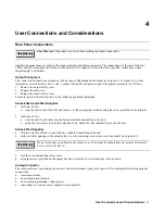
Страница 31: ...t does not see Appendix B B Use a screwdriver to remove the line fuse from the fuseholder 1 Figure 2 1 Verify that the fuse is as specified on the label Replace the fuse III Check that the SENSE switch 4 Figure 4 1 is set to Local IV Make sure that there is no load connected to the output and terminals 2 Figure 4 2 Series 657xA Power Supplies I Examine the Line Voltage label 4 Figure 2 2 and verif...

Страница 32: ... Some of the front panel keys perform two functions one labeled in black and the other in blue You access the blue function by first pressing the blue key which is not labeled When the Shift annunciator is on you will know you have access to the key s shifted blue function Backspace Key The key is an erase key If you make a mistake entering a number and have not yet entered it have not pressed you...

Страница 33: ...de displays output voltage Press several times Voltage drops about 5 millivolts each time you press the key Press the same number of times Voltage increases about 5 millivolts each time you press the key Rotate the Voltage control first counterclockwise and then clockwise Control operates similarly to the and keys Turning the controls more quickly causes a more rapid change in voltage Press 0V 22 ...

Страница 34: ...urrent to low Press Dis annunciator goes off CC annunciator comes on and AMPS display shows some current If there is no current and CV annunciator remains on increase the operating voltage setting Press several times Current increases about 7 milliamperes each time you press the key Press the same number of times Current decreases about 7 milliamperes each time you press the key Rotate the Current...

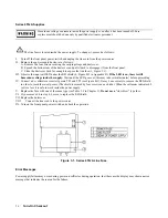
Страница 35: ...sing n Save this value to location 1 by pressing n Remove the output voltage by pressing This recalls the power supply values stored in location 0 which are the factory reset values see Chapter 5 for more information n Press and notice that the output voltage returns to 5 In Case Of Trouble Line Fuse If the power supply appears dead with a blank display and the fan not running first check your pow...

Страница 36: ... on there is still hazardous voltage inside the supply Wait until the LED goes out this may take several minutes before proceeding IV Connect a dc voltmeter across test points TP1 and TP2 see Figure B 3 It may be necessary to remove the RFI shield in order to reach these test points The shield is secured by four screws on each side When the voltmeter indicates 60 volts or less it is safe to work i...

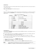
Страница 37: ...mbient thermistor reading E12 DACS Secondary VDAC IDAC readback Checksum Errors If the display shows EE CHKSUM the power supply has detected an EEPROM checksum error A checksum error can occur due to the following conditions n Excessive number of write cycles to an EEPROM see Supplemental Characteristics This condition which would appear only after extended use is not recoverable and requires serv...

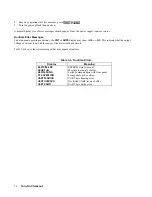
Страница 38: ...L or OL This indicates that the output voltage or current is beyond the range of the meter readback circuit Table 3 4 shows other error messages that may appear at runtime Table 3 4 Runtime Errors Display Meaning EE WRITE ERR EEPROM status time out SBUB FULL Message too long for buffer SERIAL DOWN Failed communication with front panel STK OVERFLOW Front panel stack overflow UART FRAMING UART byte ...

Страница 39: ... Series 654xA strip the end of each load wire and secure it to the appropriate terminal using the screw provided on the terminal On Series 655xA strip the end of each load wire and fasten a suitable terminal lug to the end using the screws provided on the output bus bars attach the wire terminal lugs to the bus bars Series 657xA Supplies strip the end of each load wire and fasten a suitable termin...

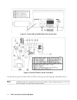
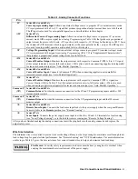
Страница 40: ... 657xA Rear Panel Connections The connector accepts wire sizes from AWG 22 to AWG 12 The purpose of each analog pin is described in Table 4 1 Note In addition to specific wiring instructions given in this chapter it is good engineering practice to twist and shield all signal wires to and from the analog connector ...

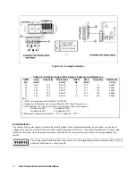
Страница 41: ...ing supplies in autoparallel for increased current output see Auto Parallel Operation IM Series 657xA Current Monitor Output Monitors the output current with respect to Common P P A signal see Current Monitor IM in Table 1 2b at this output indicates a zero to full scale current IM is also used when connecting supplies in autoparallel for increased current output see Auto Parallel Operation Common...

Страница 42: ...pper wire 3 With bundled wires use the following percentages of the rated ampacity 2 conductors 94 4 conductors 83 3 conductors 89 5 conductors 76 4 Maximum temperatures ambient 50 C conductor l05 C Output Isolation The output of the power supply is isolated from earth ground Either output terminal may be grounded or an external voltage source may be connected between either output and ground Howe...

Страница 43: ...he total internal see Inductive Loads and external capacitance These momentary crossovers into CC mode will not damage the supply Inductive Loads Inductive loads provide no loop stability problems in CV mode However in CC mode inductive loads will form a parallel resonance network with the power supply s output capacitor Generally this will not affect the stability of the supply but it may cause r...

Страница 44: ...y s voltage readback occurs at the sense terminals Figure 4 4 Multiple Load Connections Remote Sensing Optional Local Voltage Sensing Your power supply was shipped set up for local sensing This means that the supply will sense and regulate its output at the output terminals not at the load Since local sensing does not compensate for voltage drops across screw terminals bus bars or load leads local...

Страница 45: ...ce noise pickup CV Regulation The voltage load regulation specification in Performance Specifications applies at the output terminals of the power supply When remote sensing this specification must be compensated as follows Series 654xA and 655xA Supplies Add 3 mV to the voltage load regulation specification for each 1 volt change in the positive load lead due to a change in load current Because t...

Страница 46: ...lems associated with load lead inductance This leaves load load lead resistance and load capacitance as the major source of reduced stability Further improvement to the stability of the supply may be obtained by keeping the load capacitance as small as possible and by decreasing the load lead resistance by using larger diameter wires However if heavy gauge wire AWG 10 is used conditions may arise ...

Страница 47: ...the absolute voltage difference between the output terminal of the master supply and the output terminal of the first slave supply is kept under 2 V at rated current This also applies to the voltage difference between the output terminals of the first and second slave supplies If remote sensing is required connect the load to the remote sense terminals of the master supply as shown by the dashed l...

Страница 48: ... The following technique minimizes the chance that the slave 2 OVP circuit will trip 1 Program the OVP level of the master and of slave 1 to the desired protection level below the maximum level specified in Table 1 2b 2 Program the OV protection level of slave 2 to its maximum value Enable OCP on the Master You can do this if the combination of all three supplies is being used in the CV mode and t...

Страница 49: ...urrent in excess of the supply s maximum reverse diode current see Supplemental Characteristics External Voltage Control The setup shown in Figure 4 9 allows an external dc voltage to program the power supply output A voltage applied to the voltage programming input programs the output voltage and a voltage applied to the current programming input programs the output current See Figure 4 3 and Tab...

Страница 50: ...en voltage programming the output the frequency of the programming source is limited by the slew rate of the power supply To keep the power supply from slewing its output going into nonlinear operation the maximum programming rate is 3750 V s The maximum downprogramming rate when the power supply is sinking current is 750 V s These restrictions can be expressed as the maximum programming frequency...

Страница 51: ...or the output is programmed below the battery voltage the power supply will continuously sink a large current from the battery This could damage the supply To avoid this insert a reverse blocking diode in series with the output of the supply Connect the diode cathode to the battery terminal and the diode anode to the supply output terminal The diode may require a heat sink Series 654xA and 655xA L...

Страница 52: ......

Страница 53: ...You also can calibrate the power supply from the front panel see Appendix A Getting Acquainted The front panel is summarized in Figure 5 1 Note that the panel is organized as follows LCD display including annunciators Output VOLTAGE and CURRENT rotary RPG controls SYSTEM keys FUNCTION keys ENTRY keys Power On Off LINE switch Some keys perform two operations The first operation is shown on the key ...

Страница 54: ...utput Rotary Controls Voltage Rotate clockwise to increase output voltage or program setting Provides the same function as the and keys Current Rotate clockwise to increase output current or program setting Provides the same function as the and keys 3 SYSTEM Keys Not used2 Not used2 Not used2 Press to restore a previously saved power supply state Use ENTRY keys through to specify which location to...

Страница 55: ... the OV trip voltage setting After pressing you may use the ENTRY keys to change the value 5 ENTRY Keys Press to increment the output voltage in the CV mode or the voltage setting after you have pressed the key 3 Press to decrement the output voltage in the CV mode or the voltage setting after you have pressed the key 3 Press to increment the output current in the CC mode or the current setting af...

Страница 56: ... of Chapter 1 If you attempt to enter a value not in a valid range the entry will be ignored and OUT OF RANGE appears on the display Figure 5 2 shows the general response of a typical power supply Note that the Series 654xA and 655xA supplies have a small negative current area This is for downprogramming purposes Always keep the output current within the positive area and within the boundaries of ...

Страница 57: ...tage by pressing or rotating the Voltage control clockwise Note that the voltage increases by a specific increment depending on the voltage resolution each time you press the key and increases rapidly as you hold down the key To lower the voltage press or rotate the Voltage control counterclockwise Try to program a voltage greater than the VMAX for your supply Note that the display shows OUT OF RA...

Страница 58: ...s RL C in Figure 5 2 The supply will vary the output current to maintain a constant voltage of 25 volts If the load resistance is 0 8 ohms the supply will vary its output voltage to maintain a constant current output of 25 amperes However if you reprogram the output voltage to a lower value Vs see Figure 5 2 then the supply will again be able to maintain CV operation with the lesser load resistanc...

Страница 59: ...ate normally until it is forced into CC operation If that occurs the power supply will remove its output Checking OCP Operation The easiest way to check this operation at any specified current is to place a short across the output If the supply is connected to an Agilent Electronic Load press its key The power supply output will then drop to zero and the Prot annunciator will come on There is now ...

Страница 60: ...mory The programming parameters that are saved are Output voltage Output current OVP voltage OCP state on or off Output state enabled or disabled As an example set up the following state Voltage 4 V Current 1 A OVP voltage 5 5 V OCP on OCP annunciator on Output Off Dis annunciator on Save the above state to location 1 by pressing Now set up the following state Voltage 8 V Current 1 5 A OVP voltage...

Страница 61: ... to that stored in location 0 5 From now on the supply will always turn on to the state defined in location 0 Whenever you wish you can return the power supply to the original factory reset state To do this simply hold down the key when you turn on the supply The display indicates RST PWR ON to verify that the power supply has configured its turn on state to the original reset state From now on it...

Страница 62: ......

Страница 63: ...9230 100 Agilent 6553A 54A 55A 0 1 Ω 0 04 15 A 100 W Guildline 9230 15 Agilent 6571A 0 001 Ω 0 04 300 A 100 W Guildline 9230 300 Agilent 6572A 73A 74A 75A 0 01 Ω 0 04 100 A 100 W Guildline 9230 100 General Procedure Because the power supply output must be enabled during calibration voltages or currents hazardous to personnel and or dangerous to equipment can appear at the output terminals Paramete...

Страница 64: ...ys and that the test equipment is connected Entering the Calibration Values Use the procedure in Table A 2 for entering new calibration values Saving the Calibration Constants Storing the calibration constants overwrites the existing ones in nonvolatile memory If you are not absolutely sure that you want to store the new constants omit this step The power supply calibration constants then will rem...

Страница 65: ...occurs If the computed constant is out of acceptable range an error occurs The power supply is now holding the new OVP calibration constant in RAM Meter mode OVPCAL CAL COMPLETE N0T CV M0DE DOES NOT CAL Entering Current Calibration Values 1 Make certain appropriate shunt resistor see Table A 1 is the only load on the power supply 2 Select the first calibration point by pressing If the power supply...

Страница 66: ...n enabled it will be disabled when you turn it back on Calibration Error Messages The following error messages may appear during calibration Table A 3 Calibration Error Messages CAL ERR0R An entered value is not within acceptable range D0ES N0T CAL Computed calibration constant is out of range PASSWD ERROR You entered an incorrect password WR0NG M0DE The power supply is not in CV or CC mode as req...

Страница 67: ...f the ac power and disconnect the power cord 2 Remove the four screws securing the carrying straps and dustcover 3 Slide the dustcover back far enough to expose the line select switches see Figure B l or the line select jumpers see Figure B 2 4 On a Series 654xA supply move the line select switches to the positions corresponding to the desired voltage see Figure B 1 5 On a Series 655xA supply move...

Страница 68: ...e it from the front panel 4 Slide the dustcover back far enough to expose the line select switch see Figure B 3 5 Observe the input rail LED under the RFI shield If the LED is on there is still hazardous voltage inside the supply Wait until the LED goes out this may take several minutes before proceeding 6 Connect a dc voltmeter across test points TP1 and TP2 It may be necessary to remove the RFI ...

Страница 69: ...lation 51 annunciators Addr 54 Cal 54 64 CC 12 54 CV 12 54 Dis 32 33 54 Err 54 OCP 54 Prot 33 54 58 59 Rmt 56 Shift 35 54 SRQ 54 Unr 54 60 B backspace key 34 55 57 C key 64 66 key 65 66 key 64 calibration password 37 64 capacitive loads 43 CC mode 13 43 55 57 58 checkout output 34 power on 32 checksum error 37 key 55 Common P return 41 50 51 CURRENT control 12 32 55 key 55 keys 34 55 58 CV mode 13...

Страница 70: ...er on 37 runtime 38 selftest 37 exhaust fan 28 external voltage control 41 49 F factory reset state 61 front panel controls and indicators 12 54 programming 13 32 33 56 57 58 59 fuse line 25 27 28 31 35 36 G ground chassis 42 49 earth 11 29 42 safety 42 H hardware 25 27 I key 65 IM output 41 impedance output 19 20 24 programming source 50 inductive loads 43 initial conditions 56 ...

Страница 71: ...ance 43 isolation 51 line 13 multiple 44 key 54 local sense switch see switch sense local sensing 31 44 LS terminals 31 44 45 M manual change sheet 27 manual instruction 11 25 N N0 GPIB message 54 O OC 12 55 59 OCP 48 59 key 5 2 5 7 OL 38 OT 12 55 output characteristic 13 18 23 56 impedance 19 20 24 44 isolation 42 noise 46 oscillations 46 47 50 rating 12 46 ringing 43 stability 43 46 ...

Страница 72: ...odes 48 SCR 49 59 P key 64 power cord 11 27 29 power receptacle 11 power options 11 16 21 key 34 55 58 59 key 55 59 PWR ON INIT message 32 R rack mount kit 11 27 key 54 recalling states 45 60 remote sensing 45 51 remote sense switch see switch sense resistor shunt see shunt calibration reverse voltage 49 RFI shield 36 suppression 17 23 ringing output 4 5 RPG control see CURRENT and VOLTAGE control...

Страница 73: ...5 65 shift key 34 53 54 56 shunt calibration 63 slide mount rack 12 specifications 14 21 supplemental characteristics 15 22 supplies in auto parallel 47 48 supplies in series 49 support rails 27 switch line voltage 67 68 sense 31 40 44 45 T turn on state factory reset 61 stored location 0 60 U unregulated output 60 V key 65 verification tests 31 63 VOLTAGE control 12 32 54 57 key 55 keys 33 55 57 ...

Страница 74: ......

Страница 75: ...26 U S A tel 305 267 4245 fax 305 267 4286 Canada Agilent Technologies Canada Inc 5150 Spectrum Way Mississauga Ontario L4W 5G1 tel 1 877 894 4414 Australia New Zealand Agilent Technologies Australia Pty Ltd 347 Burwood Highway Forest Hill Victoria 3131 tel 1 800 629 485 Australia fax 61 3 9272 0749 tel 0 800 738 378 New Zealand fax 64 4 802 6881 Europe Agilent Technologies Test Measurement Europe...

Страница 76: ...ormation for Series 654xA has been updated as per IEC 61010 1 requirements throughout the manual The Declarations of Conformity for all models have been updated 7 16 04 A note has been added to the specifications on page 14 The Declarations of Conformity for all models have been updated 5 04 09 A URL has been added to the declarations pages to obtain the latest declaration of conformity Option 841...

Отзывы: