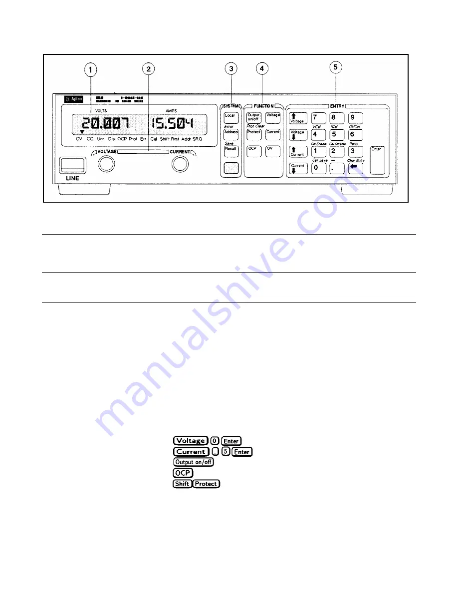
Front Panel Operation
56
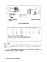
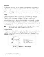
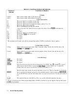
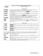
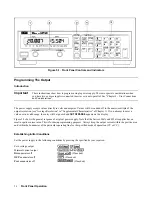
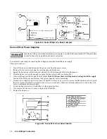
Figure 5-1. Front Panel Controls and Indicators
Programming The Output
Introduction
Important
These instructions show how to program a single power supply. There are special considerations when
you have two or more supplies connected in series or in auto-parallel. See “Chapter 4 - User Connections
and Considerations”.
The power supply accepts values directly in volts and amperes. Values will be rounded off to the nearest multiple of the
output resolution (see “Average Resolution” in “'Supplemental Characteristics” of Chapter 1). If you attempt to enter a
value not in a valid range, the entry will be ignored and
OUT OF RANGE
appears on the display.
Figure 5-2 shows the general response of a typical power supply. Note that the Series 654xA and 655xA supplies have a
small negative current area. This is for downprogramming purposes. Always keep the output current within the positive area
and within the boundaries of the particular operating line for the specified mode of operation (CV or CC).
Establishing Initial Conditions
Set the power supply to the following conditions by pressing the specified keys as required:
Zero voltage output
Minimal current output
Dis
annuciator off
(If needed)
OCP
annunciator off
(If needed)
Prot
annunciator off
(If needed)

