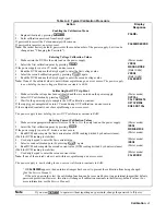
Front Panel Operation
54
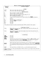
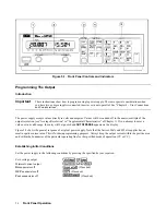
Table 5-1. Front Panel Controls and Indicators
Control or
Indicator
Function or Indication
1 Display
VOLTS
Shows present output voltage of the power supply.
AMPS
Shows present output current of the power supply.
Status Annunciators
CV
The power supply is in constant-voltage mode.
CC
The power supply is in constant-current mode.
Unr
The power supply output is unregulated (output is neither CV or CC).
Dis
The power supply output is disabled.
OCP
The overcurrent protection function is enabled.
Prot
A protection circuit has caused the power supply to shut down. (Press
to determine the
reason.).
Err
(Not used
1
).
Cal
The power supply is in calibration mode.
Shift
The shift key
has been pressed.
Rmt
(Not used
1
)
Addr
(Not used
1
)
SRQ
(Not used
1
)
1
These annunciators function only with the corresponding models of GPIB System family of power supplies.
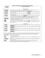
2 Output Rotary Controls
Voltage
Rotate clockwise to increase output voltage or program setting. Provides the same function as the
and
keys.
Current
Rotate clockwise to increase output current or program setting. Provides the same function as the
and
keys.
3 SYSTEM Keys
(Not used
2
)
(Not used
2
)
(Not used
2
)
Press to restore a previously saved power supply state. Use ENTRY keys
through
to specify
which location to recall. (Select by pressing
.) Use the ENTRY keys to specify the
location where you want to store the state. You may use locations 0 to 4.
Note
: Location 0 may contain the power supply turn-on state. See “Turn-On Operation” in this chapter.
Use to save the power supply's present state to nonvolatile memory. (Select by pressing
.)
Use the ENTRY keys to specify the location where you want to store the state. You may use locations 0
to 4.
This unlabeled blue key is the Shift key. Press to access the shifted (alternate) key functions.
2
These keys function only with the corresponding models of GPIB System family of power supplies. Pressing them causes
NO GPIB
to be displayed.

