


Maintenance
Soloist HPe 50/75/100
Chapter 6: Maintenance
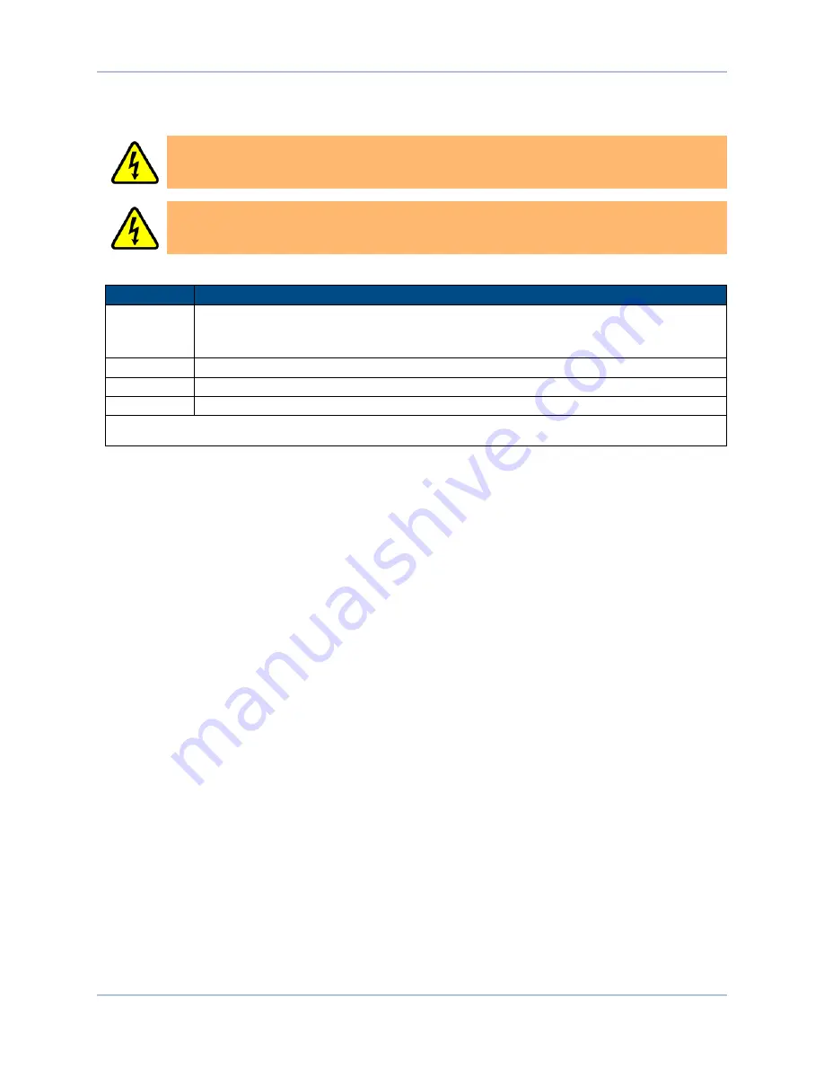
D A N G E R : Always disconnect the Mains power connection before opening the Soloist HPe
50/75/100 chassis.
D A N G E R : Before performing any tests, be aware of lethal voltages inside the controller and
at the input and output power connections. A qualified service technician or electrician should
perform these tests.
Table 6-1:
LED Description
LED
Description
ENB/FLT
Turns green to indicate that the axis is enabled. Turns red to indicate a fault condition. The
ENB/FLT LED will flash between RED and GREEN if the drive is enabled and in a fault
condition.
MARKER
Turns green to indicate that the marker input is high.
PWR*
Turns green when power is applied.
POS
Turns green to indicate that the axis is in position.
* If the power light flashes continuously and the unit does not operate, there is too much current draw from the 5V power supply or
the control supply voltage level is low.
www.aerotech.com
Chapter 6
95
Содержание Soloist HPe 100
Страница 1: ...Revision 4 09 00 Soloist HPe 50 75 100 Hardware Manual ...
Страница 14: ...Soloist HPe 50 75 100 Quick Installation Guide 14 www aerotech com This page intentionally left blank ...
Страница 24: ...Soloist HPe 50 75 100 Introduction 24 Chapter 1 www aerotech com This page intentionally left blank ...
Страница 57: ...Installation and Configuration Soloist HPe 50 75 100 Figure 2 26 PSO Interface www aerotech com Chapter 2 57 ...
Страница 94: ...94 Chapter 5 www aerotech com Soloist HPe 50 75 100 Accessories This page intentionally left blank ...
Страница 100: ...100 Chapter 6 www aerotech com Soloist HPe 50 75 100 Maintenance This page intentionally left blank ...
Страница 104: ...Soloist HPe 50 75 100 Revision History 104 Appendix B www aerotech com This page intentionally left blank ...


