


66
Chapter 2
www.aerotech.com
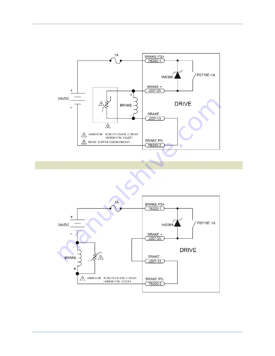
is an example of a +24 VDC brake connected to the Motor Feedback connector. In this example
the ex24 VDC power source is connected to TB202.
Figure 2-34:
Brake Connected to J207
N O T E :
The user is responsible for providing fuse protection for the brake circuit.
is an example of a 24 VDC brake connected to TB202. The user must connect J207 pin 13 to
J207 pin 25. In this case, J207 would function as an interlock to prevent the brake from releasing if the Motor
Feedback connector is not connected.
Figure 2-35:
Brake Connected to TB202
Soloist HPe 50/75/100
Installation and Configuration
Содержание Soloist HPe 100
Страница 1: ...Revision 4 09 00 Soloist HPe 50 75 100 Hardware Manual ...
Страница 14: ...Soloist HPe 50 75 100 Quick Installation Guide 14 www aerotech com This page intentionally left blank ...
Страница 24: ...Soloist HPe 50 75 100 Introduction 24 Chapter 1 www aerotech com This page intentionally left blank ...
Страница 57: ...Installation and Configuration Soloist HPe 50 75 100 Figure 2 26 PSO Interface www aerotech com Chapter 2 57 ...
Страница 94: ...94 Chapter 5 www aerotech com Soloist HPe 50 75 100 Accessories This page intentionally left blank ...
Страница 100: ...100 Chapter 6 www aerotech com Soloist HPe 50 75 100 Maintenance This page intentionally left blank ...
Страница 104: ...Soloist HPe 50 75 100 Revision History 104 Appendix B www aerotech com This page intentionally left blank ...


