Chapter 10 The High-Capacity 1U HiveManager Appliance
100
Aerohive
Ethernet and Console Ports
The two operational 10/100/1000-Mbps Ethernet ports use standard RJ45 connector pin assignments that
follow the TIA/EIA-568-B standard (see
). They accept standard types of Ethernet
cable—cat3, cat5, cat5e, or cat6. Because the ports have autosensing capabilities, the wiring termination in
the Ethernet cables can be either straight-through or crossover. Port 1 is reserved for management
connections, while port 2 is reserved for LAN connections.
Through the RJ45 Console port, you can make a serial connection between your management system and
the HiveManager appliance. The pin-to-signal mapping is described in
"RJ45 Console Port Pin Assignments"
.
The serial connection settings are:
•
Bits per second: 9600
•
Data bits: 8
•
Parity: none
•
Stop bits: 1
•
Flow control: none
The default login name is
admin
and the password is
Aerohive
. After making a connection, you can
access the Linux operating system.
Status LEDs
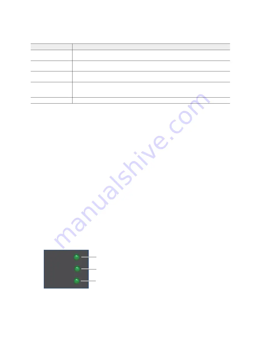
The LEDs on the front panel of the HiveManager appliance indicate the status for power and hard disk drive
activity through their color (dark or green) and illumination patterns (steady glow or blinking). The meanings
of the color and patterns for these LEDs are shown in
Figure 2 Front panel LEDs
Ethernet ports
The two operational Ethernet ports are compatible with 10/100/1000 Mbps
connections. See
"Ethernet and Console Ports" on page 100
.
Cooling fans
System fans and a power supply fan maintain an optimum operating temperature.
Be sure that air flow through the fan ducts is not obstructed.
Serial number label
The serial number label contains the FCC compliance stamp, model number, input
power specifications, and serial number for the device.
AC power inlet
The three-prong AC power inlet is a C14 chassis plug through which you can
connect the device to a 100 – 240-volt AC power source using the 10-amp/125-volt
IEC power cord that ships with the product.
On/Off switch
The on ( | ) and off (
) switch controls the power to the HiveManager Appliance.
Table 5 HiveManager Appliance component descriptions (Continued)
Component
Description
Power:
Dark: no power
Steady green: Powered
HDD:
Dark: Idle
Green (blinking): Active
POWER
STATUS
HDD
Status:
Green: Normal operation
Red: System malfunction
Содержание BR200-WP
Страница 1: ...Aerohive Hardware Reference Guide...
Страница 2: ......
Страница 10: ...Contents 8 Aerohive...
Страница 28: ...Chapter 2 AP121 and AP141 Platforms 26 Aerohive...
Страница 42: ...Chapter 3 The AP170 Platform 40 Aerohive...
Страница 74: ...Chapter 6 AP330 and AP350 Platforms 72 Aerohive...
Страница 98: ...Chapter 9 BR200 and BR200 WP Routers 96 Aerohive...
Страница 110: ...Chapter 11 The HiveManager Platform 108 Aerohive...
Страница 124: ...Index 122 Aerohive...


