background image

Hardware Reference Guide

77

M

OUNTING


THE

 AP340

Plenum Mount

To mount the AP340 in the plenum space above a dropped ceiling grid, you need the mounting plate, 

hanger clip, and a standard 24"-wide hanger frame, which can be ordered separately (SKU# 
AH-ACC-BKT-PLENUM).
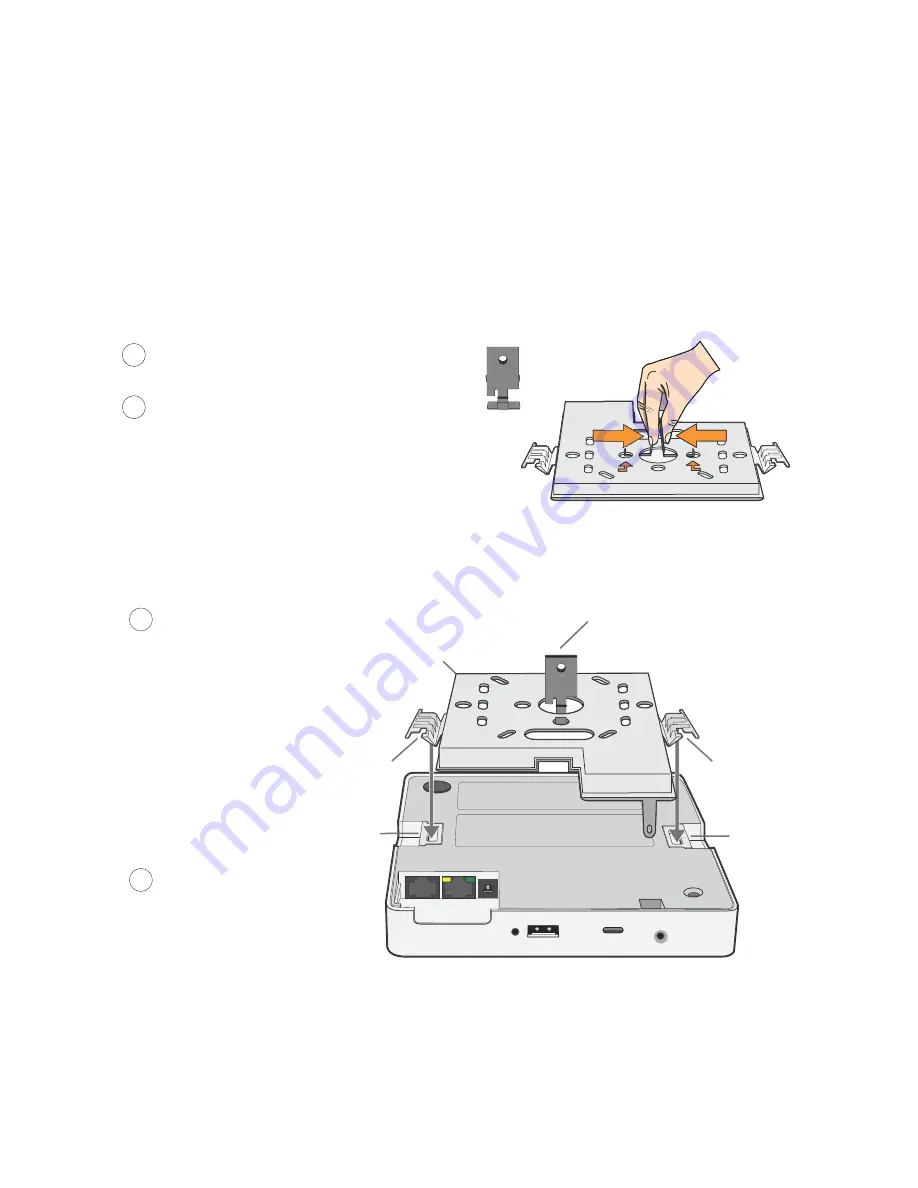
1. With the recessed side of the mounting plate facing downward, insert the hanger clip through the large 

hole in the center of the plate.

2. Squeeze the clip until the projecting tabs at the ends of its two feet snap into the smaller holes on both 

sides of the larger hole (see 

Figure 12

).

Figure 12  Fitting the hanger clip to the mounting plate

3. Attach the AP340 to the mounting plate, and then attach the antennas to the connectors (see 

Figure 13

).

Figure 13  Attaching the AP340 to the mounting plate

4. Remove the ceiling tile next to the area where you want to mount the device.
5. Press the hanger frame downward into place on the ceiling track until the claws on each leg grips the 

track below the top ridge (see 

Figure 14

).

Insert the hanger clip through the large hole in 
the mounting plate.

Squeeze the hanger clip to pull the tabs on the 
feet inward until they snap upward into the two 
holes on either side of the larger hole.

1

2

Hanger clip


Align the V-shaped tabs on the 
mounting bracket with the tab 
slots on the bottom of the AP.

Insert the V-shaped tabs into the 
tab slots until they click into place.

Attach external antennas, if they 
are required. (The AP shown 
here uses internal antennas.)

Mounting plate

Tab slot

V-shaped tab

V-shaped tab

Tab slot

Hanger clip

3

4

Содержание Aerohive AP141

Страница 1: ...Aerohive Hardware Reference Guide ...

Страница 2: ...ed Aerohive Networks the Aerohive Networks logo HiveOS HiveAP and HiveManager are trademarks of Aerohive Networks Inc All other trademarks and registered trademarks are the property of their respective companies Information in this document is subject to change without notice No part of this document may be reproduced or transmitted in any form or by any means electronic or mechanical for any purp...

Страница 3: ...uide describes Aerohive hardware devices including component descriptions installation and mounting instructions wiring diagrams and hardware specifications for each device This guide is a useful resource for all Aerohive administrators ...

Страница 4: ...Kit Contents Required Accessories and Tools 20 Safety Instructions and Site Hazard Warnings 20 Mounting the AP170 21 Vertical Pole Mount 22 Horizontal Pole Mount 23 Flat Surface Mount 24 Attaching External Antennas 25 Attaching the Ethernet Cable Waterproof Housing 26 PoE and Ethernet Protection 26 Accessing the Internal Reset Switch 28 Device Power and Environmental Specifications 29 Chapter 3 AP...

Страница 5: ...tion 53 Device Power and Environmental Specifications 54 Chapter 6 BR200 and BR200 WP Routers 55 Product Overview 56 Radio and Antennas 58 Ethernet and Console Ports 58 USB Modem Port 59 BR200 WP PoE LAN Ports 59 Status LEDs 60 Mounting and Installation 60 Device Power and Environmental Specifications 61 Chapter 7 The AP340 Platform 63 AP340 Product Overview 64 Ethernet and Console Ports 66 Smart ...

Страница 6: ...e Mount 89 Device Power and Environmental Specifications 90 Chapter 9 The HiveManager Platform 91 Product Overview 92 Ethernet and Console Ports 93 Status LEDs 94 Rack Mounting the HiveManager 95 Device Power and Environmental Specifications 96 Chapter 10 The High Capacity HiveManager 97 Product Overview 98 Rack Mounting the High Capacity HiveManager 100 Replacing Power Supplies 103 Replacing Hard...

Страница 7: ...Contents 6 Aerohive ...

Страница 8: ...te up to 300 Mbps per radio The AP121 has four internal antennas and the AP141 has four detachable external antennas two 2 4 GHz and two 5 GHz in both cases Both models have an RJ 45 10 100 1000 Ethernet port an RJ 45 console port and a USB modem port reserved for future use This chapter covers the following topics relating to the AP121 and AP141 AP121 and AP141 Product Overview on page 8 Ethernet...

Страница 9: ...tion Status Indicator The status indicator conveys operational states for system power firmware updates Ethernet and wireless interface activity and major alarms For details see Status Indicator on page 10 2 4 and 5 GHz RP SMA connectors AP141 You can connect up to four detachable single band antennas two 2 4 GHz and two 5 GHz to the male 802 11a b g n RP SMA reverse polarity subminiature version ...

Страница 10: ...h 10 100 1000Base T TX and automatically negotiates half and full duplex connections with the connecting device It is autosensing and adjusts to straight through and cross over Ethernet cables automatically For details see Ethernet and Console Ports on page 10 Reset Button The reset button allows you to reboot the device or reset it to its factory default settings Insert a paper clip or similar to...

Страница 11: ... console port you can make a serial connection between your management system and the AP The pin to signal mapping of the RJ 45 console port is the same as that for the AP340 which is shown in Figure 2 on page 66 Similarly cabling and connection details for the AP121 and AP141 are the same as those for the AP340 see Figure 2 on page 11 Status Indicator The AP121 and AP141 have a triangular status ...

Страница 12: ... omnidirectional and provide fairly equal coverage in all directions in a toroidal donut shaped pattern The antennas and connectors are labeled for easy identification and connection and swivel in all directions as shown in Figure 2 Figure 2 AP141 antenna articulation and labels For optimal coverage align the antennas as shown in Figure 3 For more information about configuring antennas for the bes...

Страница 13: ...s the power and Ethernet cables as shown in Figure 4 Figure 4 Attaching the rail mounting bracket to a ceiling track For narrower tracks you can order a pair of 9 16 rail mounts for AP121 AP141 AP330 and AP350 models from Aerohive AH ACC 9 16 CLIP 330 AP350 The kit contains a bracket for flush ceilings and a bracket for recessed ceilings You can slide the mounting bracket along the ceiling track i...

Страница 14: ...ty tab extension Security screw cavity Tab slot Tab slot V shaped tab V shaped tab Side view Security tab slot Security screw cavity Tab slot Tab slot Security tab extension V shaped tab V shaped tab Bird s eye view 2 3 1 With the two flexible V shaped tabs at the sides of the plate extending away from the surface attach the mounting plate to a secure object such as a wall ceiling post or beam Cut...

Страница 15: ...w you will need a drilled spanner insert bit for size 6 security screws and a screw driver that will accept the bit The correct bits are available from Aerohive in sets of three for AP121 AP141 AP330 and AP350 models AH ACC SEC BIT 330 AP350 3PK If you use the slotted screw you can install it with a standard flat blade screwdriver or pan head driver bit 1 Insert the security screw or slotted screw...

Страница 16: ...D 170 mm W x 41 mm H x 185 6 mm D Weight AP121 11 6 oz 0 36 kg AP141 13 5 oz 0 42 kg Antennas AP121 Two internal omnidirectional 802 11b g n antennas and two internal omnidirectional 802 11a n antennas AP141 Two 2 4 GHz and two 5 GHz external omnidirectional 802 11b g n articulated antennas Console serial port RJ 45 9600 bits per second 8 data bits parity none 1 stop bits no flow control Ethernet ...

Страница 17: ...Chapter 1 AP121 and AP141 Platforms 16 Aerohive ...

Страница 18: ...PoE Power over Ethernet that follows the IEEE 802 3at standard This chapter covers the following topics relating to the AP170 device AP170 Product Overview on page 18 Ethernet Port on page 19 Antennas on page 19 Installing the AP170 on page 20 Kit Contents Required Accessories and Tools on page 20 Safety Instructions and Site Hazard Warnings on page 20 Mounting the AP170 on page 21 Vertical Pole M...

Страница 19: ...ding lugs four antenna connectors and a waterproof 10 100 1000 Ethernet connector The device ships with a complete mounting kit see Kit Contents Required Accessories and Tools on page 20 Outdoor antennas The AP170 supports four external antennas two 2 4 GHz band IEEE 802 11b g n with a 5 dBi gain and two 5 GHz band IEEE 802 11a n with a 7 dBi gain You can order antennas from Aerohive AH ACC 170 AN...

Страница 20: ...he device so that the antennas are vertical The two 2 4 GHz antennas link to a 2 4 GHz radio for 802 11b g n and the two 5 GHz antennas link to the a 5 GHz radio for 802 11a n The two radios can operate concurrently Although hive members automatically adjust their signal strength according to their environments you can manually resize the area of coverage by increasing or decreasing the signal str...

Страница 21: ...not place the AP170 within 8 20 cm of people when using the omnidirectional antennas that ship with the product If you are using a point to point mesh directional antenna do not place the AP170 within 26 65 cm of people You can install the AP170 in wet windy locations Therefore make sure to install the Ethernet cable housing for a complete waterproof connection To protect the AP170 from lightning ...

Страница 22: ...lled out Do not locate the AP170 enclosure near overhead power lines or other electric light or power circuits or where it can come into contact with such circuits During installation exercise extreme care not to come into contact with these circuits which can cause serious injury or death For proper installation and grounding of the product refer to national and local electrical codes NFPA Nation...

Страница 23: ...he hose strap around the pole and tighten the clamp with a 1 4 2 cm slotted screwdriver or a 5 16 8 mm drive socket or nut driver 5 Connect the grounding cable to the grounding lug on the unit as shown in Figure 5 on page 25 Connect the other end of the cable to an appropriate ground Plane bracket Base bracket 1 2 Attach the base bracket to the plane bracket using 4 1 4 6 mm round head screws with...

Страница 24: ...riate ground When attaching the AP170 to a horizontal pole such as the arm of a street light make sure that the face of the device is perpendicular to the Earth for optimal RF coverage Figure 4 Correct and incorrect orientation of the AP170 when mounted to a horizontal pole Plane bracket Base bracket 1 2 Attach the plane bracket to the back of the unit using 4 3 8 x 1 2 10 mm x 13 mm hex head bolt...

Страница 25: ... nut lock washer and flat washer on each bolt to tighten the unit to the surface As you tighten the nuts the flanges on the back of the bolt sleeve will expand in the hole securing the device in place 6 Connect the grounding cable to the grounding lug on the unit as shown in Figure 5 on page 25 Connect the other end of the cable to an appropriate ground If you are not installing the device on a co...

Страница 26: ...e and antennas are labeled To connect the antennas screw them onto the antenna connectors by hand turning them clockwise until tight It is extremely important to properly ground your device to complete your installation You do not need to use a tool to tighten the antennas or apply self amalgamating PTFE polytetrafluoroethylene tape around the threads of the connectors to create a waterproof seal ...

Страница 27: ...ng onto the threaded connector cover 7 Connect the other end of the Ethernet cable to a PoE injector or Ethernet protector Figure 6 Ethernet housing assembly POE AND ETHERNET PROTECTION In most cases you can connect an Ethernet cable directly from the AP170 to a PoE enabled switch or to a PoE injector SKU AH ACC INJ 30W XX inside the building In some cases you might need to install an outdoor wate...

Страница 28: ... 8 Connecting the Ethernet protection device SKU AH ACC 1G ETH PROT Ethernet Protector Ethernet Protector Ethernet Protector Outdoor PoE injector Indoor PoE Injector PoE Switch Switch Indoors This arrangement does not require an Ethernet protector because it is built into the outdoor PoE injector AP170 outdoors Ethernet cable Wireless link To network To network Switch To network To network through...

Страница 29: ...ge of the switch to depress the switch mechanism Hold this position for a minimum of 10 seconds to reset the device See Figure 9 Figure 9 The AP170 internal reset switch 3 Replace the top being careful not to disturb the weatherproofing gaskets 4 Tighten the six screws to secure the top to the chassis Be very careful not to disturb the black rubber and woven metal gaskets when removing or replacin...

Страница 30: ... antennas 6 05 lb 2 744 kg with antennas and brackets Antennas 4 N type female connectors for external antennas Ethernet connector autosensing 10 100 1000 Base T Mbps compliant with the IEEE 802 3at standard for PoE Mounting options Horizontal or vertical pole mount pole must be 1 to 3 5 2 5 cm to 8 9 cm in diameter Wall or flat surface mount Power Specifications PoE nominal input voltages 48 V 30...

Страница 31: ...Chapter 2 The AP170 Platform 30 Aerohive ...

Страница 32: ... PoE Power over Ethernet that follows the IEEE 802 3af standard or the 802 3at pre standard Optionally they can be powered by an AC DC desktop power adapter This chapter covers the following topics relating to the AP100 series AP110 and AP120 Product Overview on page 32 Ethernet Port on page 33 Status Indicator on page 34 Antennas on page 34 Mounting an AP110 or AP120 on page 35 Ceiling Mount on p...

Страница 33: ... descriptions Figure 1 AP110 and AP120 hardware components Table 1 AP110 and AP120 component descriptions Component Description Status Indicator The status indicator conveys operational states for system power firmware updates Ethernet and wireless interface activity and major alarms For details see Status Indicator on page 34 Device Lock Slot You can physically secure the AP by attaching a Kensin...

Страница 34: ... button reset config enable Pressing the button between 1 and 5 seconds will still reboot the AP but pressing it for more than 5 seconds will not reset its configuration ETH0 PoE Port The 10 100 1000 Mbps Ethernet port ETH0 receives an RJ 45 connector The AP can receive power through an Ethernet connection to the ETH0 port from PSE power sourcing equipment that is compatible with the 802 3af stand...

Страница 35: ...e Configuration Advanced Configuration Management Services Management Options page Through the CLI enter no system led brightness soft dim off The four settings are represented graphically in Figure 2 Figure 2 Adjustable status indicator brightness levels Antennas Antennas are an integral part of both the AP110 and AP120 The AP110 has two internal dual band antennas The AP120 has four internal sin...

Страница 36: ...abs grip the track ensures that the clip does not snap into place prematurely with only one tab in position Figure 4 Attaching the track clip to the ceiling track 3 Twist the track clip until it snaps onto the ceiling track as shown in Figure 5 You can then slide the clip along the track to reposition it if necessary Figure 5 Securing the clip to the track and repositioning it if necessary You can...

Страница 37: ...ngage the locking mechanism Figure 7 Figure 7 Locking the AP with a Kensington security lock You can also mount the AP to a solid ceiling or the underside of any horizontal object such as a cross beam using three 6 or 8 screws Position the three screws in a T shaped layout two screws 2 5 cm apart from each other and the third screw center aligned between them and 4 75 12 cm away Then attach the AP...

Страница 38: ...e wall from the port side of the AP which is located at the top of the device when it is mounted on a wall You can use a Kensington lock to secure the AP to a stationary object For information see Locking the AP on page 36 Wall 1 2 3 4 Position two 6 or 8 screws 2 5 cm apart and fasten them to a secure object such as a wall post or beam Cut or drill a hole in the wall 1 2 2 5 5 cm above the screws...

Страница 39: ...W x 2 H x 6 5 D 16 3 cm W x 4 6 cm H x 16 3 cm D Weight 1 75 lb 0 8 kg Antennas AP110 two dual band omnidirectional 802 11a b g n antennas AP120 two omnidirectional 802 11b g n antennas and two omnidirectional 802 11a n antennas Ethernet port one autosensing 10 100 1000 Base T TX Mbps port compliant with the IEEE 802 3af and 802 at standards for PoE Power over Ethernet Power Specifications DC Inpu...

Страница 40: ...CS23 data rates they can provide a PHY data rate up to 450 Mbps per radio The AP330 has internal antennas and the AP350 has detachable external antennas They both have dual 10 100 1000 Ethernet ports for link aggregation or link redundancy Their systems can accept power from either an 802 3af or 802 3at standard PoE Power over Ethernet power injector or from an AC DC power adapter connected to a 1...

Страница 41: ... that have white ribbed rings and are labelled 2 4 GHz to the connectors that are labelled 2 4 GHz Connect the antennas that have gray knurled rings and are labelled 5 GHz to the connectors that are labelled 5 GHz and are encircled by a gray line For details see Antennas on page 43 Console port You can access the CLI by making a serial connection to the RJ 45 console port The management station fr...

Страница 42: ...P to its factory default settings Insert a paper clip or something similar into the Reset pinhole and press the reset button To reboot the device hold the button down for 5 seconds To return the configuration to the factory default settings hold it down for at least 10 seconds After releasing the button the Power LED goes dark and then glows steady amber while the firmware loads and the system per...

Страница 43: ...rt you can make a serial connection between your management system and the AP The pin to signal mapping of the RJ 45 console port is the same as that for the AP340 which is shown in Figure 2 on page 66 Similarly cabling and connection details for the AP330 and AP350 are the same as those for the AP340 see Figure 3 on page 69 USB Modem Port When configured as routers AP330 and AP350 devices can use...

Страница 44: ...lated 2 4 GHz and 5 GHz antennas have a 2 dBi gain These antennas are omnidirectional providing fairly equal coverage in all directions in a toroidal donut shaped pattern For greater coverage on a horizontal plane it is best to orient the antennas vertically So that you can easily do this whether the AP is mounted horizontally or vertically the articulated antennas hinge and swivel The non articul...

Страница 45: ...haped tabs and the security tab extension on the rail mount with the two tab slots and the security screw cavity on the underside of the AP and then push the AP upward until it clicks into place as shown in Figure 5 on page 45 For narrower tracks you can order a pair of 9 16 rail mounts from Aerohive AH ACC 9 16 CLIP 330 AP350 One rail mount in the pair is flush and the other is recessed You can s...

Страница 46: ...ess the AP upward until it snaps into place 4 Security tab extension Security screw cavity Tab slot Tab slot V shaped tab V shaped tab side view Security screw cavity Tab slot Tab slot Security tab extension V shaped tab V shaped tab Bird s eye view 2 3 1 With the two flexible V shaped tabs at the sides of the plate extending away from the surface attach the mounging plate to a secure object such ...

Страница 47: ...fasten the screw to the security tab extension on the rail mount as shown in Figure 7 for the AP330 If you want to expose the USB port use the security screw without the cover Figure 7 Locking the AP330 to the mounting plate 3 With the insert bit in a screwdriver tighten the screw into place to secure the device to the plate DEVICE POWER AND ENVIRONMENTAL SPECIFICATIONS Understanding the range of ...

Страница 48: ...put pins Wires 4 5 7 8 or 1 2 3 6 Environmental Specifications AP330 Operating temperature 32 to 104 degrees F 0 to 40 degrees C Storage temperature 40 to 185 degrees F 40 to 85 degrees C Relative Humidity Maximum 95 noncondensing AP350 Operating temperature 4 to 131 degrees F 20 to 55 degrees C Storage temperature 40 to 185 degrees F 40 to 85 degrees C Relative Humidity Maximum 95 noncondensing ...

Страница 49: ...Chapter 4 AP330 and AP350 Platforms 48 Aerohive ...

Страница 50: ...Layer 3 network capability with local DHCP and DNS services centralized management and firewall and VPN security This chapter covers the following topics relating to the BR100 router Product Overview on page 50 Radio and Antennas on page 52 USB Modem Port on page 52 Mounting and Installation on page 53 Device Power and Environmental Specifications on page 54 Power Specifications on page 54 Environ...

Страница 51: ...ter hardware components Each component is described in Table 1 BR100 router component descriptions Figure 1 The BR100 router hardware components Table 1 BR100 router component descriptions Component Description Device status LED The device status LED is located on the triangular wedge on the top of the device This LED conveys operational states for system power firmware upgrades connectivity with ...

Страница 52: ...e description the ports to which it applies and optional security and filtering rules For information about how to configure a LAN profile refer to HiveManager Help Reset button The reset button allows you to reboot the device or reinstate the default settings or to a bootstrap configuration if you have configured one Insert a paper clip or similar tool into the Reset pinhole and press the reset b...

Страница 53: ... the 3G wireless network AT T Shockwave Sierra Wireless USBConnect 308 to connect to the 3G wireless network Verizon Pantech UML290 to connect to the 4G LTE network Before you can use a modem with an Aerohive device you must first have the modem activated You can have this done in the store where you purchased the modem or you can install software such as the Verizon VZA Access Manager on your com...

Страница 54: ...ng a firmware upgrade Do not turn the device off while the LED is flashing White steady The device has made a CAPWAP connection to HiveManager and is operating properly White flashing Device is operating in a failover state using the USB modem Link Status LEDs Dark No link Green steady The Ethernet link is up but inactive Green flashing The Ethernet link is up and active MOUNTING AND INSTALLATION ...

Страница 55: ...78 g Antennas Two embedded single band omnidirectional 802 11b g n antennas Ethernet ports One IEEE 802 3 10BASE T and IEEE 802 3u 100BASE TX compliant 10 100 Mbps RJ 45 Fast Ethernet WAN port Four IEEE 802 3 10Base T and IEEE 802 3u 100BASE TX compliant 10 100 Mbps RJ 45 LAN ports with autosensing and auto MDI MDI X IEEE 802 3x PAUSE frame flow control in full duplex USB connector One Type A USB ...

Страница 56: ...and firewall and IPsec VPN security There are two BR200 models the BR200 and the BR200 WP This chapter covers the following topics relating to Aerohive BR200 series routers Product Overview on page 56 Radio and Antennas on page 58 USB Modem Port on page 59 BR200 WP PoE LAN Ports on page 59 Status LEDs on page 60 Mounting and Installation on page 60 Device Power and Environmental Specifications on ...

Страница 57: ...H0 four LAN ports ETH1 through ETH4 a Console Port and a USB port for WAN connection redundancy The BR200 series routers support up to 16 SSIDs BR200 WP only 16 VLANs 16 networks and 64 user profiles across both wired and wireless interfaces Figure 1 shows the BR200 series router hardware components Each component is described in Table 1 BR200 series routers component descriptions on page 57 Figur...

Страница 58: ...raight through and cross over Ethernet cables automatically On BR200 WP models the ETH1 and ETH2 ports also provide 802 3af and 802 3at PoE support to powered devices For more information see BR200 WP PoE LAN Ports on page 59 To provide Ethernet connections to devices on the LAN side connect the ETH 1 ETH 4 interfaces on the router to a switch or host On BR200 series routers each of these ports re...

Страница 59: ...the Ethernet cable can be either straight through or cross over Use the RJ 45 console port to make a serial connection between your management system and the router USB modem connector The Type A USB 2 0 port backward compatible with USB1 1 allows you to connect a wireless 3G 4G USB modem to serve as a backup WAN connection For locations where an Ethernet connection to the WAN is not possible you ...

Страница 60: ...ere 802 3af PoE provides up to 12 95 W of DC power to each device this rate reflects normal power loss through the cables 802 3af meets the power demands of PoE Class 0 1 2 and 3 devices 802 3at PoE provides up to 25 5 W of DC power to each device this rate reflects normal power loss through the cables 802 3at meets the power demands of PoE Class 4 devices The BR200 WP router balances PoE power ou...

Страница 61: ... Dark No link Green steady The Ethernet link is up but inactive at 1000 Mbps Green flashing The Ethernet link is up and active at 1000 Mbps Amber steady The Ethernet link is up but inactive at 10 100 Mbps Amber flashing The Ethernet link is up and active at 10 100 Mbps PoE Status LEDs BR200 WP Dark No power is being provided through the port Green steady Port is delivering PoE normally to powered ...

Страница 62: ... single band omnidirectional 802 11b g n antennas Ethernet ports One IEEE 802 3 10BASE T IEEE 802 3u 100BASE TX and IEEE 802 3ab 1000BASE T compliant 10 100 1000 Mbps RJ 45 Fast Ethernet WAN port Four IEEE 802 3 802 3u and 802 3ab compliant 10 100 1000 Mbps RJ 45 LAN ports with autosensing and auto MDI MDI X IEEE 802 3x PAUSE frame flow control in full duplex For BR200 WP models ports 1 and 2 are ...

Страница 63: ...Chapter 6 BR200 and BR200 WP Routers 62 Aerohive ...

Страница 64: ...led smart PoE Power over Ethernet to adjust its power consumption automatically in response the available power in different environments Smart PoE supports the IEEE 802 3af standard and the 802 3at pre standard This chapter covers the following topics relating to the AP340 AP340 Product Overview on page 64 Ethernet and Console Ports on page 66 Status LEDs on page 70 Antennas on page 70 Mounting t...

Страница 65: ...ching a lock and cable such as a Kensington notebook lock to the device lock slot or by using the lock adapter that is included in the mounting kit and a padlock For more information see Locking the AP340 on page 76 802 11a b g n RP SMA Connectors You can connect up to six detachable single band antennas to the male 802 11a b g n RP SMA reverse polarity subminiature version A connectors Connect th...

Страница 66: ...t is available as an extra option Because the AP does not have an on off switch connecting it to a power source automatically powers on the device Console Port You can access the CLI by making a serial connection to the RJ 45 console port The management station from which you make a serial connection to the AP must have a VT100 emulation program such as Tera Term Pro a free terminal emulator or Hi...

Страница 67: ...in MDI MDI X MDI or MDI X 1 2 3 4 1 Transmit DC DC DC1 DC1 DC1 DC1 2 Transmit DC DC DC1 DC1 DC1 DC1 3 Receive DC DC DC1 DC1 DC1 DC1 4 unused DC DC2 DC2 DC2 DC2 5 unused DC DC2 DC2 DC2 DC2 6 Receive DC DC DC1 DC1 DC1 DC1 7 unused DC DC2 DC2 DC2 DC2 8 unused DC DC2 DC2 DC2 DC2 MDI Medium dependent interface for straight through connec ions MDI X Medium dependent interface for cross over X connection...

Страница 68: ...ted to the network and are in backhaul mode the AP transmits broadcast traffic only through ETH0 The AP transmits broadcast traffic through ETH1 only when ETH0 does not have network connectivity When both Ethernet interfaces are connected to the network and are in access mode then the AP transmits broadcast traffic through all the access interfaces ETH0 ETH1 and all wireless subinterfaces in acces...

Страница 69: ...mands interface eth0 bind red0 primary interface eth1 bind red0 The interface that you specify as primary is the one that the AP uses when both interfaces have network connectivity Because the AP uses eth0 as the primary interface by default it is unnecessary to specify primary in the first command above However it is included to make the role of eth0 as the primary interface obvious Interface Sel...

Страница 70: ... Console Port Pin SIgnal Direction 1 RTS Request to Send Output unused 2 DTR Data Terminal Ready Output unused 3 TXD Transmitted Data Output 4 Ground Ground 5 Ground Ground 6 RXD Received Data Input 7 DSR Data Set Ready Input unused 8 CTS Clear to Send Input unused Because this is a console port only pins 3 4 5 and 6 are currently in use Table 3 Wiring information for a serial cable with RJ 45 to ...

Страница 71: ...ace is in access mode and active Amber steady Wireless interface is in backhaul mode but inactive Amber flashing Wireless interface is in backhaul mode and is connected with other hive members Green and amber alternating Wireless interface is in backhaul mode and is searching for other hive members Antennas The AP340 can accept up to six detachable dipole antennas The three shorter antennas are de...

Страница 72: ...ttom Aerohive devices accommodate external antennas via coaxial jacks on the chassis see Antennas on page 70 These jacks are standard male RP SMA connectors Coverage patterns are not perfect for these antennas and they often broadcast slightly in directions other than the primary one These extra lobes can be seen in both of the patterns shown below 5 GHz Antenna for IEEE 802 11a n Length when full...

Страница 73: ...802 11n standard in which multiple RF links are formed on the same channel between the transmitter and receiver simultaneously To accomplish this the transmitter separates a single data stream into multiple spatial streams one for each RF chain an antenna various digital signal processing modules linked to the antenna The transmit antennas at the end of each RF chain then transmit their spatial st...

Страница 74: ...rocessors in the multiple receive chains are able to combine their processing efforts to sort through all the received data and reconstruct the original message Furthermore because the transmitter makes use of multiple RF chains there is an even richer supply of signals for the receive chains to use in their processing To set the transmit and receive RF chains for a radio profile enter the followi...

Страница 75: ...eed of 802 11a b g client traffic Although 802 11a b g client traffic can benefit somewhat from an 802 11n access point using MIMO supporting such legacy clients along with 802 11n clients can have a negative impact on 802 11n client traffic Legacy clients take longer to send the same amount of data as 802 11n clients Consequently legacy clients consume more airtime than 802 11n clients do causing...

Страница 76: ... fasten the mounting plate to the clips as shown in Figure 9 When you have the mounting plate in the correct location cut or drill a hole in the ceiling through which you can then pass the Ethernet and power cables Figure 9 Attaching the track clips and mounting plate to the ceiling track Attach the AP340 to the mounting plate and connect the cables as shown in Figure 10 on page 76 You can also mo...

Страница 77: ...e 11 Locking the AP340 to the mounting plate 2 Link a padlock through the opening in the adapter and engage the lock to secure the AP340 to the mounting plate The opening is 1 8 0 3 cm in diameter at its narrowest You can tie the cables to the tie points small arched strips on the mounting plate to prevent them from being pulled out of their connections accidentally With the AP upside down align i...

Страница 78: ... antennas to the connectors see Figure 13 Figure 13 Attaching the AP340 to the mounting plate 4 Remove the ceiling tile next to the area where you want to mount the device 5 Press the hanger frame downward into place on the ceiling track until the claws on each leg grips the track below the top ridge see Figure 14 Insert the hanger clip through the large hole in the mounting plate Squeeze the hang...

Страница 79: ...es to the network and if not using PoE connect the power cord to a power source 8 Replace the ceiling tile to complete the installation Hanger frame 5 4 Remove the ceiling tile and enter the plenum Press the hanger frame onto the ceiling track Bird s eye view with the ceiling tiles and ceiling tracks removed for clarity AP attached to the mounting plate 6 Insert the hanger clip up through the cent...

Страница 80: ...ow on its side and then pass it through the loop at the end of the quad toggle 5 Insert the wire rope back through the center hole in the locking device and then continue pulling it through the locking device until the AP340 is suspended at the height you want see Figure 17 on page 80 The center tube that runs through the locking device is designed to allow you to pull the rope wire up through it ...

Страница 81: ...ted While maintaining pressure on the tube adjust the rope until the AP340 is at the height you want When you are satisfied stop pressing against the tube so that it can regain its grip on the rope Figure 18 Releasing the wire rope from the locking device Clip 3 Wrap the wire rope around a beam clip the hook to the rope and then pull the rope down until it is taut against the beam Pull downward on...

Страница 82: ...ut of their connections accidentally Mounting plate AP Wall Orient the mounting plate as shown and attach it to a secure object such as a wall post or beam Use 8 screws for the oblong holes or 10 screws for the larger round holes Cut or drill a hole through the large space near the bottom of the mounting plate to pass the cables through to the AP Insert the tabs on the mounting plate into the slot...

Страница 83: ...ight 3 lb 1 36 kg Antennas Three omnidirectional 802 11b g n antennas and three omnidirectional 802 11a n antennas Serial port RJ 45 bits per second 9600 data bits 8 parity none stop bits 1 flow control none Ethernet ports autosensing 10 100 1000 Base T TX Mbps both ports are compliant with the IEEE 802 3af and 802 at standards for PoE Power over Ethernet Power Specifications AC DC power adapter I...

Страница 84: ...nsumption automatically in response to the available power in different environments Smart PoE supports the IEEE 802 3af and 802 3at standards This chapter covers the following topics relating to the AP320 AP320 Product Overview on page 84 Ethernet and Console Ports on page 86 Status LEDs on page 86 Antennas on page 87 Mounting the AP320 on page 87 Ceiling Mount on page 88 Surface Mount on page 89...

Страница 85: ...tional states for system power firmware Ethernet interfaces and radios For details see Status LEDs on page 86 ETH0 10 100 1000 Mbps PoE Port and ETH1 10 100 1000 Mbps Port The two 10 100 1000 Mbps Ethernet ports ETH0 and ETH1 receive RJ 45 connectors The AP320 can receive power through an Ethernet connection to the ETH0 port from PSE power sourcing equipment that is compatible with the 802 3af and...

Страница 86: ...rial connection settings bits per second 9600 data bits 8 parity none stop bits 1 flow control none For details see Ethernet and Console Ports on page 86 Device Lock Slot You can physically secure the AP320 by attaching it to a mounting plate that is clipped to a ceiling track and then using a screw with a unique head design to fasten the AP320 to the mounting plate through the device lock slot Th...

Страница 87: ...l connection between your management system and the Aerohive device The pin to signal mapping of the RJ 45 console port is the same as that for the AP340 which is shown in Figure 3 on page 69 Similarly cabling and connection details for the AP320 are the same as those for the AP340 see Figure 3 on page 69 Status LEDs The five status LEDs on the top of the AP320 indicate various states of activity ...

Страница 88: ...cy range 5 GHz for IEEE 802 11a These interface to radio relationships are permanent Although hive members automatically adjust their signal strength according to their environments you can resize the area of coverage by increasing or decreasing the signal strength manually by entering the interface wifi0 wifi1 radio power number command where number can be from 1 to 20 and represents a value in d...

Страница 89: ...djust the ceiling tiles back into their former position For clarity the power and Ethernet cables are not shown in the illustrations Ceiling track Track clips Mounting plate 3 1 Press the clips against the ceiling track and swivel them until they snap into place gripping the edges of the track If necessary slide the clips and mounting plate along the track until they are in the spot you want Then ...

Страница 90: ... to the surface Then through the large opening in the lower part of the plate make a hole in the wall so that you can pass the cables through to the AP Finally attach the device to the plate and connect the cables as shown in Figure 6 Figure 6 Mounting the AP320 on a wall Security screw Ceiling track Mounting plate AP Note The ceiling tiles are removed for clarity Orient the mounting plate as show...

Страница 91: ...ennas and three omnidirectional 802 11a n antennas Serial port RJ 45 bits per second 9600 data bits 8 parity none stop bits 1 flow control none Ethernet ports two autosensing 10 100 1000 Base T TX Mbps ports the ETH0 port is compliant with the IEEE 802 3af and 802 at standards for PoE Power over Ethernet Power Specifications AC DC power adapter Input 100 240 VAC Output 48V 0 38A PoE nominal input ...

Страница 92: ... management of up to 500 devices Profile based configurations that simplify the deployment of large numbers of devices Scheduled firmware upgrades on devices by location Exportation of detailed information on devices for reporting This chapter covers the following topics related to the HiveManager platform Product Overview on page 92 Ethernet and Console Ports on page 93 Status LEDs on page 94 Rac...

Страница 93: ...The status LEDs convey operational states for the system power and hard disk drive For details see Status LEDs on page 94 MGT and LAN Ethernet Ports The MGT and LAN Ethernet ports are compatible with 10 100 1000 Mbps connections automatically negotiate half and full duplex mode with the connecting devices and support RJ 45 connectors They are autosensing and automatically adjust to straight throug...

Страница 94: ...yperterminal provided with Windows operating systems AC Power Inlet The three prong AC power inlet is a C14 chassis plug through which you can connect a HiveManager to a 100 240 volt AC power source using the 10 amp 125 volt IEC power cord that ships with the product On Off Switch The on and off switch controls the power to the HiveManager Power Fan The fan that maintains the temperature of the po...

Страница 95: ...gure 4 Figure 4 Status LEDs 1 2 3 4 5 6 7 8 9 Male DB 9 console port View of the console port on HiveManager Pin Signal Direction 1 DCD Data Carrier Detect unused 2 RXD Received Data Input 3 TXD Transmitted Data Output 4 DTR Data Terminal Ready unused 5 Ground Ground 6 DSR Data Set Ready unused 7 RTS Request to Send unused 8 CTS Clear to Send unused 9 RI Ring Indicator unused The above pin assignm...

Страница 96: ...5 Depending on the layout of your equipment rack you might need to mount the HiveManager in reverse To do that move the brackets to the left and right sides near the rear before mounting it Figure 5 Mounting the HiveManager in an equipment rack 1 Position the HiveManager so that the holes in the mounting brackets align with two mounting holes in the equipment rack rails 2 Insert a screw through a ...

Страница 97: ... x 15 13 16 D 42 7 cm W x 4 4 cm H x 40 2 cm D Weight 13 75 lb 6 24 kg Serial port male DB 9 RS 232 port bits per second 9600 data bits 8 parity none stop bits 1 flow control none USB port standard Type A USB 2 0 port Ethernet ports MGT and LAN autosensing 10 100 1000 Base T Mbps Power Specifications ATX Advanced Technology Extended autoswitching power supply with PFC power factor corrector Input ...

Страница 98: ...file based configurations that simplify the deployment of large numbers of devices Scheduled firmware upgrades on devices by location Exportation of detailed information on devices for reporting Hot swappable power supplies Cold swappable hard disk drives This chapter covers the following topics related to the High Capacity HiveManager platform Product Overview on page 98 Rack Mounting the High Ca...

Страница 99: ...ontain first level RAID Redundant Array of Independent Drives mirrored hard disk drives to provide fault tolerance data reliability and increased performance Front Mounting Brackets When used with the rack mounting kit the two front mounting brackets allow you to mount the High Capacity HiveManager in a standard 19 48 26 cm equipment rack For rack mounting instructions see Rack Mounting the High C...

Страница 100: ...ity HiveManager see Ethernet and Console Ports on page 42 Reset Button The reset button allows you to reboot the High Capacity HiveManager Insert a paper clip or something similar into the hole and press the reset button between 1 and 5 seconds After releasing the button the Power LED goes dark and then glows steady amber while the software loads and the system performs a self test After the softw...

Страница 101: ...ound holes 1 After checking that the mounting kit contains the above parts separate the chassis rails from each slide set as shown in Figure 2 Figure 2 Separating the chassis rail from the nested slides 2 Position one of the chassis rails so that the slide stop is near the HiveManager mounting bracket near the front panel and the front and rear holes in the chassis rail align with the holes in the...

Страница 102: ...the rack For round holes use the cross head screws to fasten the brackets through the holes in the rack rails to the bar nuts You can use the locator pins to help keep the bar nuts aligned to the holes See Figure 5 Figure 5 Fastening the rear mounting brackets to the rack rails Place the slide stop against the front mounting bracket Chassis rail Cross head machine screws with 10 32 threads Outer s...

Страница 103: ...ur screws two for each of the front brackets fasten the HiveManager to the equipment rack as shown in Figure 6 If the rack has round holes use the two remaining bar nuts and locator pins and thread the screws through the rack rails into them Figure 6 Mounting the HiveManager in an equipment rack The HiveManager is now securely mounted to the front and rear rails of the equipment rack Rack rails Re...

Страница 104: ...ply from the power source 2 Lower the handle to a horizontal position 3 With your index finger press the red release lever to the left 4 While holding the release lever to the left grip the handle between your thumb and second finger and pull the power supply straight out See Figure 7 Figure 7 Removing a power supply 5 Insert a working power supply into the vacant bay and push it straight in until...

Страница 105: ... the failed HDD and insert a replacement 5 Close and lock the door 6 Connect a serial cable to the console port 7 Connect one end of an RS 232 serial cable to the male DB 9 console port on the HiveManager and other end to the serial port or COM port on your management system 8 Start a serial connection by running a VT100 emulation program on your management system with the following settings Bits ...

Страница 106: ... in which the device can operate Device Specifications Form factor 2U rack mountable device Chassis dimensions 16 13 16 W x 3 1 2 H x 17 D 42 7 cm W x 8 9 cm H x 43 2 cm D Weight 34 lb 15 42 kg Serial port male DB 9 RS 232 port bits per second 9600 data bits 8 parity none stop bits 1 flow control none USB port standard Type A USB 2 0 port Ethernet ports MGT and LAN autosensing 10 100 1000Base T Mb...

Страница 107: ...Chapter 10 The High Capacity HiveManager 106 Aerohive ...

Страница 108: ...ity tab cavity 9 status indicator 8 10 AP141 7 15 antenna connectors 8 console 9 console port 10 environmental specifications 15 Ethernet port 9 Ethernet port LED 10 external antenna alignment 11 hardware specifications 15 locking 9 14 mounting ceiling 12 mounting surface 13 power connector 9 power specifications 15 reset button 9 security screw cavity 13 security tab cavity 9 status indicator 8 1...

Страница 109: ... 51 power specifications 54 radio 52 reset button 51 USB modem connector 51 WAN port 51 BR200 series 55 61 console 57 58 device and enclosure specifications 61 device status LED 57 60 environmental specifications 61 Ethernet ports 57 58 hardware specifications 61 link status LED 57 60 locking 58 mounting and installation 60 power connector 57 power specifications 61 product overview 56 reset butto...

Страница 110: ...PoE 67 R radios See individual platform entries reboot APs 9 32 41 65 85 redundant interfaces 68 reset config 9 32 41 65 85 routes default route selection 68 S serial port See individual platform entries smart PoE 67 status LEDs See individual platform entries ...

Страница 111: ...Index 110 Aerohive ...

Отзывы: