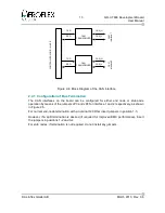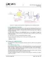
16
GR-UT699 Development Board
User Manual
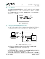
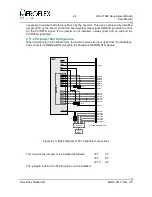
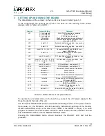
2.6 Serial Interface
The
UT699RH
ASIC, provides a single Serial port, with TXD/RXD pins, and the
GR-UT699
board provides an RS232 driver/receiver chip and routes these signals to a front panel
connector.
The front panel connector type for the UART interface is Female D-Sub 9 pin type with a
standard pin-out for serial links.
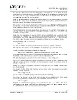
2.7 Debug Support Unit (DSU) Serial Interface
The
GR-UT699
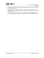
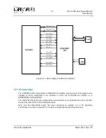
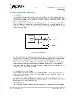
unit provides a interface for Debug and control of the processor by means of
a host terminal via the DSU serial link to the
UT699
ASIC, as represented in Figure 2-8.
The board provides two possibilities for connecting to the processor's DSU interface:
1. USB MiniAB connector with USB to Serial interface chip
2. JTAG DSU interface
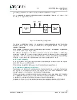
The baud rate of the serial link is specified by the host computer, and the DSU interface in
the
UT699
ASIC auto-detects and adjusts its baud rate to suit.
The
DSUENable
signal input to the processor is connected to a jumper on the PCB. In
© Aeroflex Gaisler AB
March 2013, Rev. 0.6
Figure 2-8: Debug Support Unit connections
Figure 2-7: Serial interface
UT699RH
ASIC
DSUTX←
DSURX→
DSUBRE→
DSUACT←
DSUEN→
D
S
U
I
/F
HOST
TERMINAL/COMPUTER
USB-SERIAL
JTAG
USB to SERIAL
CONVERTER
UT699RH
ASIC
RS232
INTERFACE
SUB-D 9 pin
Female
RS232
DRIVER/
RECEIVERS
TXD
RXD
Содержание GR-UT699
Страница 1: ...GR UT699 Development Board User Manual AEROFLEX GAISLER AB Rev 0 6 2013 03 28 ...
Страница 6: ...6 GR UT699 Development Board User Manual Intentionally Blank Aeroflex Gaisler AB March 2013 Rev 0 6 ...
Страница 41: ...41 GR UT699 Development Board User Manual Aeroflex Gaisler AB March 2013 Rev 0 6 Figure 4 2 PCB Top View ...

