23
GR-UT699 Development Board
User Manual
2.12 Other Interfaces and Circuits
2.12.1 GPIO
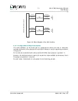
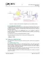
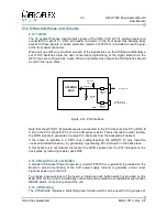
The 16 general Purpose Input Output signals of the ASIC (3.3V LVTTL voltage levels) are
connected to a set of 0.1” pitch pin header connector on the front panel thus allowing easy
access to these signals. A series protection resistor of 470 Ohm is included on each signal
at the front panel connector.
Weak pull ups (47k) are provided on each of the signals lines on the PCB and additionally a
set of DIP Switches allow the user convenient programming of the signal state when the
GPIO lines are configured as inputs. When programmed as outputs the DIP switches should
be left in the 'open' state.
Note that the GPIO[11..8] signals are also connected to the PCI Interrupt pins PCI_INT[A B
C D] on the PCI connector PCI-J1 via a 33R series resistor. This is intended in order to allow
the GPIO signals to generate or receive PCI interrupts from the backplane if desired.
If the board is installed in a CPCI rack, setting/resetting the GPIO[11..8] may therefore
cause unintended behaviour, by generating a generating PCI Interrupts on the back plane.
If this behaviour is not desired, disconnect the GPIO signals from the PCI interrupts on the
back plane by removing resistor pack R35.
2.12.2 Reset Circuit and Button
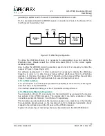
A standard Processor Power Supervisory circuit (TPS3705 or equivalent) is provided on the
Board to provide monitoring of the 3.3V power supply rail and to generate a clean reset
signal at power up of the Unit.
To provide a manual reset of the board, a miniature push button switch is provided on the
Main PCB for the control. Additionally connections are provided to an additional push-button
RESET
switch on the front panel of the unit.
2.12.3 Watchdog
The
UT699
ASIC includes a Watchdog timer function which can be used for the purpose of
© Aeroflex Gaisler AB
March 2013, Rev. 0.6
Figure 2-14: PIO interface
UT699RH
ASIC
PCB
16 GPIO[15..0]
DIP-SW
(x16)
PULL-UP
(x16)
SERIES
(x16)
GPIO[15..0]
GPIO[11..8] =
PCI_INT[A B C D ]
SERIES
(x4)
Содержание GR-UT699
Страница 1: ...GR UT699 Development Board User Manual AEROFLEX GAISLER AB Rev 0 6 2013 03 28 ...
Страница 6: ...6 GR UT699 Development Board User Manual Intentionally Blank Aeroflex Gaisler AB March 2013 Rev 0 6 ...
Страница 41: ...41 GR UT699 Development Board User Manual Aeroflex Gaisler AB March 2013 Rev 0 6 Figure 4 2 PCB Top View ...

