15
GR-UT699 Development Board
User Manual
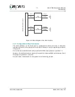
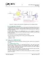
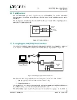
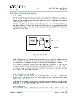
The pin out and connector types for these Spacewire interfaces conform to the Spacewire
standard, as shown in Figure 2-6.
The inner shield pin (pin3 of the connector) is connected to DGND via a Zero-ohm resistor.
2.5.2 SPWCLK
Configuration options on the board (jumpers, crystal socket and SMA coaxial connector)
allow this Spacewire clock to be provided from the following sources:
•
Dedicated
SPWCLK
oscillator (if appropriate Oscillator X3 is mounted in socket and
jumper J17 is not installed)
•
Main processor oscillator X1(if jumper J17 is installed)
•
External clock input via SMA connector J16. (X3 and J17 not installed)
The default configuration is that the clock is supplied by the SPWCLK oscillator X3, and
jumper J17 is not installed. Do not install jumper J17 if an oscillator is installed in X3 socket
as this will unintentionally connect the outputs of oscillator X1 and Oscillator X3 together.
© Aeroflex Gaisler AB
March 2013, Rev. 0.6
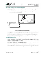
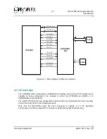
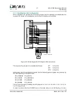
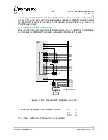
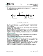
Figure 2-6: Transceiver and Termination of the SPW interfaces (2 of 4 interfaces shown)
Содержание GR-UT699
Страница 1: ...GR UT699 Development Board User Manual AEROFLEX GAISLER AB Rev 0 6 2013 03 28 ...
Страница 6: ...6 GR UT699 Development Board User Manual Intentionally Blank Aeroflex Gaisler AB March 2013 Rev 0 6 ...
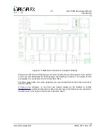
Страница 41: ...41 GR UT699 Development Board User Manual Aeroflex Gaisler AB March 2013 Rev 0 6 Figure 4 2 PCB Top View ...


