13
GR-UT699 Development Board
User Manual
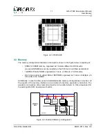
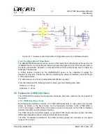
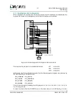
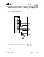
2.4.1 Configuration of Bus Termination
The CAN interfaces on the board can be configured for either end node or stub-node
operation by means of the jumpers JP3 and JP4 for interface 1 and 2 respectively, as shown
in Figure 2-5.
For normal end-node termination with a nominal 120 Ohm insert jumpers in position 1-3.
However,
if a
split termination is desired (if required for improved EMC performance), insert
the jumpers in positions 1-2 and 3-4.
For stub nodes, if termination is not required, do not install any jumpers.
© Aeroflex Gaisler AB
March 2013, Rev. 0.6
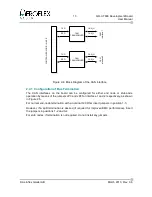
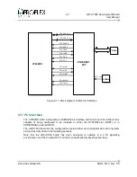
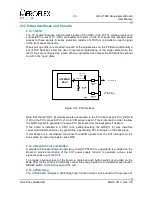
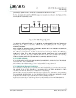
Figure 2-4: Block Diagram of the CAN interface
CAN
TRANSCEIVER
CAN
TRANSCEIVER
CAN_H
CAN_L
TXD
RXD
C
A
N
in
te
rf
ac
e
1
CAN
TRANSCEIVER
CAN
TRANSCEIVER
CAN_H
CAN_L
TXD
RXD
C
A
N
in
te
rf
ac
e
2
C
O
N
T
R
O
LL
E
R
L
O
G
IC
I
N
A
S
IC
Содержание GR-UT699
Страница 1: ...GR UT699 Development Board User Manual AEROFLEX GAISLER AB Rev 0 6 2013 03 28 ...
Страница 6: ...6 GR UT699 Development Board User Manual Intentionally Blank Aeroflex Gaisler AB March 2013 Rev 0 6 ...
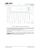
Страница 41: ...41 GR UT699 Development Board User Manual Aeroflex Gaisler AB March 2013 Rev 0 6 Figure 4 2 PCB Top View ...


