14
GR-UT699 Development Board
User Manual
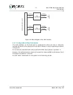
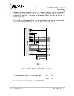
2.4.2 Configuration of Slew Rate
The SN65HVD230 transceiver device used on the board has the facility to set the device into
STANDBY
mode, by connecting an active high external signal to pin 8 of the device (refer to
the device data sheet). However, on this board this is tied to permanently
'low'
to enable the
CAN bus Transceivers.
A further feature provided by the SN65HVD230 device is the capability to adjust the
transceiver slew rate. This can be done by modifying the values of resistors connected to pin
8 of the transceivers.
The default value of 0 ohms is compatible with 1Mbps operation.
From the data sheet the following resistor values give the following slew rates:
10kOhm => 15V/us
100kOhm => 2V/us
2.5 Spacewire (LVDS) Interfaces
The
UT699
ASIC provides four Spacewire interfaces which are routed to the front panel of
the board.
2.5.1 SPW interface circuit
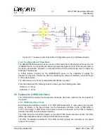
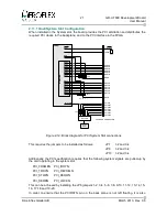
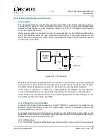
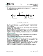
Each Spacewire interface consists of 4 LVDS differential pairs (2 input pairs and 2 output
pairs), as shown in the figure below. As the Spacewire interface to the
UT699
ASIC is
LVTTL (3.3V logic), LVDS driver and receiver circuits are required on the PCB to interface
between the ASIC and the external interface.
The PCB traces for the LVDS signals on the
GR-UT699
board are laid out with 100-Ohm
differential impedance design rules and matched trace lengths.
100 Ohm Termination resistors for the LVDS receiver signals are mounted on the board
close to the receiver.
© Aeroflex Gaisler AB
March 2013, Rev. 0.6
Figure 2-5: Transceiver and Termination Configuration (one of 2 interfaces shown)
Содержание GR-UT699
Страница 1: ...GR UT699 Development Board User Manual AEROFLEX GAISLER AB Rev 0 6 2013 03 28 ...
Страница 6: ...6 GR UT699 Development Board User Manual Intentionally Blank Aeroflex Gaisler AB March 2013 Rev 0 6 ...
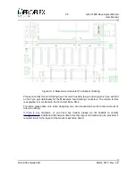
Страница 41: ...41 GR UT699 Development Board User Manual Aeroflex Gaisler AB March 2013 Rev 0 6 Figure 4 2 PCB Top View ...


