Input 1
Input 0
Input 2
Input 3
Input 4
Output 1
Output 2
Output 3
Output 4
Input 5
Input 6
Input 7
Output 5
Output 6
Output 7
Input 8
Common
Output 8
Common
Multi-Analog Box
Analog Outputs
SPS
Analog Inputs
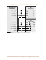
Figure H‑2. Wiring example for simple, non-differential voltage inputs
POSSIBLE WIRING FOR GALVANICALLY
SEPARATED ANALOG INPUTS
If the PLC meets the following conditions, you can avoid false measurements by
applying separate ground wires to galvanically separated ground clamps.
• The PLC has simple (non-differential) voltage and current inputs.
• The voltage input module and current input module are galvanically separated.
In case the PLC has only simple (non-differential) voltage and current inputs but the
voltage input module and current input module are galvanically separated, you can
avoid false measurements by connecting separate ground wires to their galvanically
separated ground clamps.
shows the wiring using a multi-core cable with a 7 Ω resistance per wire
(for example, 7 Ω corresponds to a 100 m [328′10″] length cable with 0.25 mm
²
wire
cross-section).
Advanced Energy
®
Impac
®
Series 600 Pyrometer
57010228-00C
Wiring Diagrams for Multiple Analog Outputs
H‑3


