background image

Grounding the Pyrometer

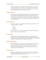
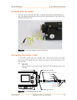
If you are using a converter box, make a suitable earth ground connection using a 
customer-supplied ground cable as shown in the following figure. This will prevent 
transmission interference.

Figure 3‑2. Ground connection for the converter box

Connecting the Sensor Cable

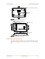
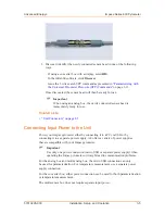
To meet EMC requirements, use a shielded cable. All AE sensor cables are shielded 
and will meet this requirement once properly connected to the terminal block on the 
converter box.

Important

If the sensor cable wires are extended, the shield of the cable also needs to be 
extended.

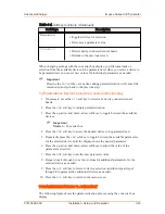
Feedthrough for cable #2

Cable wires and end sleeves

Washer

O-ring

Shield

Terminal block for cable #2

Terminal block for cable #1

Feedthrough for cable #1

Clamp screw

Sensor cable

BROWN

BLACK

BLUE

BROWN

BLACK

BLUE

Figure 3‑3. Connecting the sensor cable

Advanced Energy

®

Impac

®

 Series 600 Pyrometer

57010228-00C

Installation, Setup, and Operation

3‑3

Содержание Impac 600 Series

Страница 1: ...Impac Series 600 Pyrometer User Manual May 2022 57010228 00C...

Страница 2: ...t of the reliance on or use of the information contained herein PRODUCT USAGE STATEMENT WARNING Read this entire manual and all other publications pertaining to the work to be performed before you ins...

Страница 3: ...tive owners CUSTOMER FEEDBACK Advanced Energy s technical writing staff has carefully developed this manual using research based document design principles However improvement is ongoing and the writi...

Страница 4: ...1 Sensor Heads 2 1 Sensor Cables 2 2 Converter Box 2 2 Analog Box 2 2 Multi Sensor Box 2 2 Accessories 2 2 Unit Connectors 2 3 Sensor Head Connectors 2 3 Extension Cable Connectors 2 3 Sensor Cable C...

Страница 5: ...3 13 Parameterizing with the Universal Pyrometer Protocols UPP Commands 3 13 Parameterizing Devices Using the Converter Box Display 3 15 Parameterization Flowchart 3 16 Exposure Time 3 18 Emissivity 3...

Страница 6: ...A 600 and IGA 600 23 Pyrometer Spot Sizes C 2 Appendix D Factory Settings Appendix E Pyrometer Parameters Converter Box with Display Appendix F UPP Commands Appendix G Emissivity of Common Materials A...

Страница 7: ...C to 700 C 40 F to 1292 F MB 7 C 1 Table C 2 Optics 2N 10 1 40 C to 700 C 40 F to 1292 F MB 7 C 1 Table C 3 Optics 3N 20 1 40 C to 700 C 40 F to 1292 F MB 7 C 1 Table C 4 Optics 65 1 C 2 Table C 5 Op...

Страница 8: ...ure 3 5 Converter box display and soft keys 3 15 Figure 3 6 Parameterization process flowchart 3 17 Figure A 1 Sensor head dimensions with sensor cable A 1 Figure A 2 High temperature sensor head dime...

Страница 9: ...ic levels of hazard seriousness DANGER DANGER indicates an imminently hazardous situation that if not avoided will result in death or serious injury DANGER is limited to the most extreme situations WA...

Страница 10: ...The following labels might appear on your unit or CE label Complies with applicable European directives UK Conformity Assessed label Complies with applicable United Kingdom regulations Chassis ground...

Страница 11: ...dvancedenergy com resource library locate the entry for Pyrometer Calibration Geometry and click View Resource You can also order the directive from Beuth Verlag GmbH in D 10772 Berlin Germany https w...

Страница 12: ...tion of Chemicals Advanced Energy manufactures articles subject to Article 33 of REACH and upon request will provide information regarding Substances of Very High Concern SVHC currently identified by...

Страница 13: ...f your application It has a modular design allowing you to connect and swap multiple sensor heads With the exception of USB sensor heads your configuration will include various sensor heads and sensor...

Страница 14: ...er box can also be equipped with a display for temperature reading and parameter setting via an integrated keyboard Analog Box The analog box is an analog output only alternative to the converter box...

Страница 15: ...3 pin connector male as shown in the following figure Figure 2 1 Standard sensor head connector male Table 2 1 Sensor head connector pin assignments male Pin Wire Color 1 Brown 4 Black 3 Blue Extensio...

Страница 16: ...figure Sensor cables for connecting a sensor head directly to a PC via USB are also available These cables will not work with extension cables Sensor cables for connecting a multi sensor box to a con...

Страница 17: ...in the terminal blocks as shown in the following figure Micro USB Serial communications Signal output and power supply Sensor heads Figure 2 4 Converter box connectors Analog Box Connectors Wires for...

Страница 18: ...contacts and power supply Figure 2 6 Multi analog box connectors Multi Sensor Box Connectors Wires for each connection to the multi sensor box must be terminated and connected individually to the app...

Страница 19: ...play of temperatures and their temporal development and for setting parameters of multiple pyrometers You can use the optional MultiTempLogger Trigger software a more advanced version of the MultiTemp...

Страница 20: ...eter and the target object ensure that the window is clean and made of a material that is suitable for the wavelength of your pyrometer See Appendix G Emissivity of Common Materials Verifying the Spot...

Страница 21: ...e attach a mounting accessory to the pyrometer 2 Mount the sensor heads at a location that provides a clear view of the target object and is unobstructed by air contamination or hot reflections There...

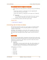
Страница 22: ...les are shielded and will meet this requirement once properly connected to the terminal block on the converter box Important If the sensor cable wires are extended the shield of the cable also needs t...

Страница 23: ...able end into the feedthrough making sure that the shield has contact with the housing and then slide the O ring and washer into the feedthrough 5 Close the feedthrough by replacing the clamp screw Th...

Страница 24: ...er either by connecting it to a PC via USB or by connecting it to a separate power supply AE offers a variety of power supplies that are compatible with your Impac pyrometer Important Use only one pow...

Страница 25: ...nts Depending on the configuration your pyrometer will be equipped with either one analog output only or multiple analog outputs only or with one digital output and one analog output Both digital outp...

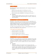
Страница 26: ...supplied cable to connect directly to the terminal block on the converter box To Connect to an RS 232 Interface 1 Connect the TxD wire to pin 3 DIG 3 2 Connect the RxD wire to pin 4 DIG 4 3 Connect th...

Страница 27: ...a WebServer call IP address 0 0 0 0 Subnet mask 0 0 0 0 Device name pyrometer To Connect to PROFINET 1 Connect the RxD wire blue wire to pin 3 DIG 3 2 Connect the RxD wire white wire to pin 4 DIG 4 3...

Страница 28: ...power supply you can connect additional analyzing devices directly to the terminal block of the converter box using either the digital interface or analog outputs Connecting Multiple Analog Outputs T...

Страница 29: ...al Once connected to the power supply the pyrometer is ready for immediate use When the pyrometer is powered on if it has a display it shows the temperatures measured by the sensor heads and the basic...

Страница 30: ...nnected and used at the same time TO SET THE CONVERTER BOX ADDRESS 1 Connect one converter box to the PC If using a converter box with a display skip this step 2 Either open a serial communication pro...

Страница 31: ...If you try to assign a sensor head address that is already assigned the CHECK ADDRESSING warning will appear on the display or in the Infra600 software Important Assigning sensor head addresses requir...

Страница 32: ...w the converter box address you can change parameters using override address 99 The pyrometer will respond to confirm that a change has been made For more information see Parameterizing with the Unive...

Страница 33: ...changed to the value of the supplied parameter the pyrometer will respond to confirm that a change has been made If you send an entry command and either omit the required data parameter or you replac...

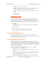
Страница 34: ...ws options for the specific function Specific tasks in this manual refer to the soft key by the menu option displayed directly above the key Converter box settings Connected sensor heads Switching con...

Страница 35: ...up arrow and down arrow soft keys to toggle between the available devices Important Master Converter box 4 Press the PAR soft key to select the desired device to be parameterized 5 Repeatedly press t...

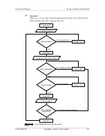
Страница 36: ...d device Displays parameter and value Press ENT Press ESC Saves changes Press PAR Desired parameter Press or Correct value Done changing parameters Yes Yes Yes Yes No change another parameter No chang...

Страница 37: ...te measurements the emissivity setting of the Impac pyrometer should be set from 10 to 100 If needed you can also use an emissivity setting of 100 to 120 to correct attenuated measurements For example...

Страница 38: ...lear time interval that is at least three times longer than the exposure time for the pyrometer to determine the highest temperature measurement Depending on the clear time interval setting the maximu...

Страница 39: ...and the maximum value for each target object must be indicated With this setting the maximum value can be stored and displayed as each target object passes the pyrometer Related Links Parameterizing...

Страница 40: ...en and close only when the measure temperature is above or below depending on the limit switch setting a value that consists of the SP1 TEMP and the adjusted hysteresis You can adjust the hysteresis s...

Страница 41: ...amage to the pyrometer can severely impact the measurement accuracy Advanced Energy recommends cleaning the pyrometer lens with isopropyl alcohol using cotton swabs or wipes or standard cloths for cle...

Страница 42: ...refer to the following checklist to identify the error and try to solve the problem Important If the Impac pyrometer is integrated in a running machine process the machine should be switched off and s...

Страница 43: ...s higher than expected Emissivity is set too low Set a higher emissivity value that corresponds to the material of the target object For more information see Emissivity on page 3 18 Measurement is bei...

Страница 44: ...ows 1 Make a note of the serial number SN and part number PN listed on the product label 2 To contact the TSO by email address your message to mailto technical support aei com In the body of the email...

Страница 45: ...uct label 2 Go to https www advancedenergy com forms rma request to display the RMA Request Form 3 Provide the required information Required fields are marked with asterisks 4 Click Next step to conti...

Страница 46: ...of the email include the serial number SN and part number PN found on the product label and a description of the reason for returning the equipment Obtaining an RMA Number by Telephone To obtain an R...

Страница 47: ...the Impac pyrometer Figure A 1 Sensor head dimensions with sensor cable Figure A 2 High temperature sensor head dimensions with sensor cable Figure A 3 Sensor head dimensions with sensor cable to USB...

Страница 48: ...Figure A 4 Converter box and multi analog box dimensions Advanced Energy Impac Series 600 Pyrometer 57010228 00C Unit Dimensional Drawings A 2...

Страница 49: ...Figure A 5 Single Analog box dimensions Advanced Energy Impac Series 600 Pyrometer 57010228 00C Unit Dimensional Drawings A 3...

Страница 50: ...Figure A 6 Multi sensor box dimensions Advanced Energy Impac Series 600 Pyrometer 57010228 00C Unit Dimensional Drawings A 4...

Страница 51: ...ions 400 g 14 1 oz Housing Sensor heads Stainless steel Converter box Aluminum Multi sensor box Aluminum Analog box Aluminum IR detector IN 600 Thermopile IS 600 Silicon photo diode Si IGA 600 Indium...

Страница 52: ...C to 1000 C 212 F to 1832 F MB 10 150 C to 1800 C 302 F to 3272 F MB 18 IN 600 5 100 C to 1300 C 212 F to 2372 F MB 13 400 C to 2500 C 752 F to 4532 F MB 25 Temperature subrange User adjustable minimu...

Страница 53: ...e following outputs RS 232 or RS 485 addressable half duplex 4800 baud to 115200 baud PROFINET I O Protocol TCP IP 100 Mbaud Resolution 0 1 C 0 1 F on the digital output 0 1 of the adjusted subrange o...

Страница 54: ...23 C and emissivity 1 Measuring temperature above the temperature measurement range The display will show OVER when the measured temperature is higher than either the basic temperature measurement ran...

Страница 55: ...sure 0 5 bar 7 25 psi Air volume 1 5 m3 h 53 ft3 h Air contaminants Use dry clean air oil and dust free ENVIRONMENTAL SPECIFICATIONS Table B 5 Standard environmental specifications Description Specifi...

Страница 56: ...g Storage temperature Converter box and multi analog box 20 C to 70 C 4 F to 158 F with non condensing conditions Sensor heads sensor cables multi sensor box and single analog box 20 C to 85 C 4 F to...

Страница 57: ...700 C 40 F to 1292 F MB 7 Measuring Distance Spot Size Distance Ratio FOV 0 4 mm 0 2 N A 70 mm 2 8 3 mm 0 1 21 2 100 mm 3 9 7 mm 0 3 15 2 200 mm 7 9 17 mm 0 7 11 8 400 mm 15 7 38 mm 1 5 10 5 600 mm 2...

Страница 58: ...mm 3 9 4 2 mm 0 165 23 200 mm 7 9 4 5 mm 0 177 44 400 mm 15 7 6 3 mm 0 248 63 600 mm 23 6 9 1 mm 0 358 65 800 mm 31 5 12 5 mm 0 492 64 IGA 600 AND IGA 600 23 PYROMETER SPOT SIZES Table C 5 Optics 70...

Страница 59: ...10 At the default baud rate of 115200 baud this means a wait time of 10 115200 seconds Clear time intervals of the maximum value storage tcl Off Measurement unit Celsius Switch contact mode Off Hyste...

Страница 60: ...ound OUT ERR Show or hide errors on the display in case of an error or wrong value at analog out SP1 MOD Select when contact shall switch OFF BELOW or OVER the selected switching temperature the tempe...

Страница 61: ...G BEG Sets the beginning of the temperature subrange Important The minimum span is 51 C 92 F S RNG END Sets the end of the temperature subrange Important The minimum span is 51 C 92 F S EMI Emissivity...

Страница 62: ...erature is higher than the maximum sensor head temperature A response of 74440 indicates that the sensor head temperature is lower than the minimum sensor head temperature Read measuring value repeate...

Страница 63: ...m1 VAL 1 is numeric Sets a new temperature measurement subrange for the sensor head The set value represents the new temperature subrange in the selected temperature scale Celsius or Fahrenheit Value...

Страница 64: ...ets the clear time interval of the maximum value storage of the sensor head Valid values are 0 to 8 0 Off 1 0 1 s 2 0 25 s 3 0 5 s 4 1 s 5 5 s 6 25 s 7 External clearing 8 Automatic clearing External...

Страница 65: ...number for the sensor head The pyrometer responds with a 7 digit decimal value Reference number AAXn bn Reports the reference number for the sensor head The pyrometer responds with a 6 character hexa...

Страница 66: ...Global address Use this address to send entry commands to all the connected pyrometers The pyrometers will not respond to confirm that a change has been made Example 98fh1 sets the temperature display...

Страница 67: ...ture in C 1 Temperature in F Model and firmware AA ve Reports the model number and firmware version for the converter box The pyrometer responds with a 6 digit value VVMMYY VV Device ID 45 Series 600...

Страница 68: ...perature is higher than the defined threshold temperature 2 Contact is switched from open to closed relay when the temperature is lower than the defined threshold temperature Source for the switch con...

Страница 69: ...for the switch contact on the converter box using a 2 character hexadecimal value The set value represents a temperature in the selected temperature scale Celsius or Fahrenheit Valid temperature is 2...

Страница 70: ...ted sensor heads in the order shown on the converter box display or in the Infra600 software A1 to A8 2 Resets all sensor head addresses Automatic addressing option AA AA VAL Toggles the automatic add...

Страница 71: ...Start YYYYYYYY End Read streaming mode AA sm The converter box responds with the streaming mode 1 digit ASCII decimal 0 Streaming off 1 Streaming on USB active 2 Streaming on RS interface active 3 St...

Страница 72: ...100 Brass oxidized tarnished 65 to 75 Brick 85 to 90 Bronze bright 3 Chamotte 45 to 60 Chromium bright 28 to 32 Copper oxidized 88 Earthenware glazed 86 to 90 Gold bright 2 Graphite 80 to 92 Nickel 22...

Страница 73: ...60 Porcelain rough 86 to 90 Silver bright 2 Slag 80 to 85 Soot 95 Steel heavily scaled 85 to 90 Steel molten 20 to 25 Steel rolling skin 80 to 88 Zinc 45 to 55 Table G 3 Emissivities for spectral ran...

Страница 74: ...ge 8 m to 14 m Target Object Material Emissivity Aluminum anodized 96 Aluminum smooth 2 to 15 Asphalt 85 Black dull varnish 95 Blackbody furnace 100 Brickwork 85 to 95 Carbon soot 95 Cement 90 Ceramic...

Страница 75: ...G 4 Emissivities for spectral range 8 m to 14 m Continued Target Object Material Emissivity Water 95 Wood 80 to 92 Advanced Energy Impac Series 600 Pyrometer 57010228 00C Emissivity of Common Material...

Страница 76: ...input of the differential voltage input This example shows simple non differential current inputs In the case of differential current inputs connect the ground for the current inputs to the negative i...

Страница 77: ...tage input The separate voltage input ground is then applied to this additional voltage input Figure H 2 shows the wiring using a multi core cable with a 7 resistance per wire for example 7 correspond...

Страница 78: ...e PLC has simple non differential voltage and current inputs The voltage input module and current input module are galvanically separated In case the PLC has only simple non differential voltage and c...

Страница 79: ...7 Output 5 Output 6 Output 7 Input 8 Common Output 8 Common Common Multi Analog Box Analog Outputs SPS Analog Inputs Figure H 3 Wiring example for galvanically separated input modules Advanced Energy...

Страница 80: ...ity 3 18 common materials G 1 emissivity table G 1 exposure time 3 18 external window optional 3 1 F factory settings D 1 flowchart parameterization 3 16 G grounding 3 3 guidelines safety 1 1 I icons...

Страница 81: ...3 hysteresis 3 21 internal temperature 3 20 mounting 3 2 3 4 power supply 3 5 protocols 3 13 10 1 sensor head address 3 12 setting parameters 3 13 specifications B 1 spot sizes 3 1 temperature display...

Страница 82: ...horized returns 4 3 wiring diagram differential voltage inputs H 1 wiring diagrams H 1 galvanically separated analog inputs H 3 non differential voltage inputs H 2 Advanced Energy Impac Series 600 Pyr...

Отзывы: