62
- FORM NO. 56043111 - Adhancer
™
ELECTRICAL SYSTEM
MAIN CONTROL PROGRAMMING OPTIONS (CONTINUED)
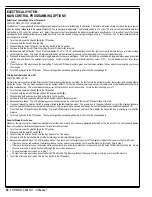
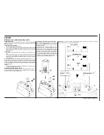
Solution Flow and Detergent Level Adjustment:
FACTORY DEFAULT: SOLUTION = ONE BAR, DETERGENT = 0.
The default solution
fl
ow rate and detergent level can be programmed to suit a particular application. To change the solution
fl
ow rate setting and detergent level,
perform the following steps:
Turn the main power Key Switch
1
(A)
to the Off position.
Press and hold the Scrub On Switch
2
(I)
and the Wand Switch
(E)
.
While holding both switches, turn the Key Switch to the On position.
3
Continue to hold the both switches until the Wand Indicator
4
(M)
and left-hand Scrub On Indicator
(K)
turn green.
Release both switches. The Scrub Off Indicator
5
(J)
will turn red, the Solution System Indicator
(O)
will turn yellow, the left-hand Scrub On Indicator
(K)
will turn
green and the display will show the solution icon with the current solution
fl
ow setting (one bar or two).
Press the Solution Switch
6
(B)
to toggle the solution
fl
ow setting between one or two bars.
Press the Scrub Off Switch to save the selected solution
fl
ow setting. The Solution System Indicator and Detergent System Indicator
7
(P)
will turn green, and the
display will show the detergent icon with a number or character (“0”, “-” or “+“) to the right of the icon. These characters in the display indicate the following:
A “0” in the display indicates that the detergent level in the solution will remain unchanged from the selected ratio setting.
A “+” (plus sign) in the display indicates that the detergent system will add an addition amount of detergent (approximately 10 percent) to the solution.
A “-” (minus sign) in the display indicates that the detergent system will reduce the amount of detergent (approximately 10 percent) in the solution.
Note:
These settings are useful if you need to add or remove a small amount of detergent to/from the solution but don’t wish to change the nominal detergent
mix ratio. For instance, if a 100:1 ratio is not giving you enough detergent for your application but a 64:1 ratio would be too much, you could select the
100:1 ratio, then select the “+” with this programming option to add an additional 10 percent of detergent to the solution.
Press the Detergent System Switch
8
(F)
to scroll the through “0”, “-“ and “+”.
Press the Scrub Off Switch to save the new setting. The Scrub Off Indicator will turn green and the display will show the key switch icon prompting you to reset
9
the machine.
Turn the Key Switch to the Off position. The new settings will be saved and will remain in effect until they are changed again.
10
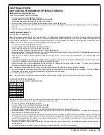
Solution Flow Icon Selection:
FACTORY DEFAULT: RECTANGULAR SHAPE
You can change the solution
fl
ow icon between a square box with one or two vertical bars, and a triangle that is either half
fi
lled or completely
fi
lled. To change the
solution
fl
ow icon, perform the following steps:
Turn the main power Key Switch
1
(A)
to the Off position.
Press and hold the Scrub On Switch
2
(I)
and Vacuum Switch
(C)
.
While holding both switches, turn the Key Switch to the On position.
3
Continue to hold the both switches until the Vacuum System Indicator
4
(N)
and both Scrub On Indicators
(K
and
L)
turn yellow.
Release both switches. The Scrub Off Indicator
5
(J)
will turn red, the Scrub On Indicators will switch off and the display will show the current solution
fl
ow icon
style.
Press the Vacuum Switch
6
(C)
to select between the two different style icons.
Press the Scrub Off Switch
7
(H)
to save the setting. The Vacuum System Indicator will turn green and the display will show the key switch icon prompting you
to reset the machine.
Turn the Key Switch to the Off position. The new setting will be saved and will remain in effect until it is changed again.
8
Содержание Adhancer 56316001(W32-C)
Страница 1: ...7 08 FORM NO 56043111 SERVICE MANUAL Models 56316000 W28 C 56316001 W32 C Adhancer...
Страница 2: ......
Страница 7: ...FORM NO 56043111 Adhancer 5 TECHNICAL SPECIFICATIONS...
Страница 25: ...FORM NO 56043111 Adhancer 23 SCRUB SYSTEM FIGURE 2...
Страница 51: ...FORM NO 56043111 Adhancer 49 FIGURE 4...
Страница 53: ...FORM NO 56043111 Adhancer 51 FIGURE 5 ELECTRICAL SYSTEM...
Страница 59: ...FORM NO 56043111 Adhancer 57 FIGURE 6 ELECTRICAL SYSTEM...
Страница 68: ......
Страница 74: ......


