14
- FORM NO. 56043111 - Adhancer
™
SOLUTION SYSTEM
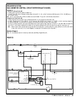
CIRCUIT OVERVIEW SOLUTION AUTO MODE (SOLENOID VALVE CIRCUIT)
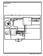
See Figure 2.
+ (Positive) circuit input starts with:
The battery positive input to the L1 solenoid coil (BRN wire).
A closed S3 key switch to direct the needed positive voltage to terminal #J1-13 - B+1 on the A1 control board (BRN wire), and to PIN 5 – KSI
(BRN wire) on the A2 Speed Controller.
- (Negative) circuit input starts with:
A battery negative ground input at A1 control board terminals B2 (J1-9), B-3 (J2-9) and B-4 (J2-6) (BLK wires).
The A1 control board solution switch enabled.
A negative voltage output from PIN #6 - BRAKE (-) on the A2 speed controller (RED/BLK wire) to terminal J1-5 – For/Rev on the A1 control board
(RED/BLK wire).
Note
: The A2 speed control BRAKE (-) output (PIN #6) occurs whenever the R1 direction throttle pot is moved off its neutral
setting.
A negative voltage output from J1-11 on the A1 control board (RED/GRN wire) to the L1 solenoid coil, turning it on to allow solution
fl
ow through
the valve body.
CIRCUIT OVERVIEW SOLUTION AUTO MODE (SOLUTION PUMP CIRCUIT)
See Figure 2.
+ (Positive) circuit input starts with:
The battery positive input to the Solution Pump Pressure Switch S1 (RED wire) on solution pump assembly.
- (Negative) circuit input starts with:
A battery negative ground input at A1 control board terminals B2 (J1-9), B-3 (J2-9) and B-4 (J2-6) (BLK wires).
The A1 control board solution button enabled.
A negative voltage output from PIN #6 – BRAKE (-) (RED/BLK wire) on the A2 speed controller to terminal J1-5 – FOR/REV. on the A1 control
board. Note that the A2 speed control BRAKE (-) output (PIN #6) occurs whenever the R1 direction throttle pot is moved off its neutral setting.
A negative voltage output from A1 board terminal J1-8 – SOL. PUMP (GRN/BLK wire) to Solution Pump M7, turning the pump on to allow
fl
ow to
Water Valve Solenoid L1.
Note:
The solution pump output volume is controlled by the A1 control board which supplies PWM (pulse width modulated) negative voltage to the
pump at a frequency of 5000 Hz. These two modulated voltage levels produce the two different solution
fl
ow rates.
The solution pump pressure switch (S1) must sense suf
fi
ciently low solution pressure in order to stay closed and allow the solution pump to
run. If the pressure switch senses high solution pressure, the switch will open and not allow positive battery voltage to the pump.
Содержание Adhancer 56316001(W32-C)
Страница 1: ...7 08 FORM NO 56043111 SERVICE MANUAL Models 56316000 W28 C 56316001 W32 C Adhancer...
Страница 2: ......
Страница 7: ...FORM NO 56043111 Adhancer 5 TECHNICAL SPECIFICATIONS...
Страница 25: ...FORM NO 56043111 Adhancer 23 SCRUB SYSTEM FIGURE 2...
Страница 51: ...FORM NO 56043111 Adhancer 49 FIGURE 4...
Страница 53: ...FORM NO 56043111 Adhancer 51 FIGURE 5 ELECTRICAL SYSTEM...
Страница 59: ...FORM NO 56043111 Adhancer 57 FIGURE 6 ELECTRICAL SYSTEM...
Страница 68: ......
Страница 74: ......


