Section 5 User Interface Guide
TRACER 6000 Series Split System Manual
78
612806320L1-1B
> E
THERNET
S
WITCH
M
ODULE
C
ONFIGURATION
/S
TATUS
/H
ISTORY
(M
AIN
S
CREEN
)
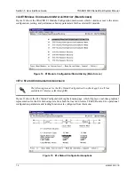
Figure 26 shows the Ethernet Switch Module Configuration/Status/History main screen, which contains
access to the status, configuration, testing, and performance history parameters for the selected Ethernet
Switch module.
Figure 26. Ethernet Switch Module Configuration/Status/History (Main Screen)
> E
THERNET
S
WITCH
C
ONFIGURATION
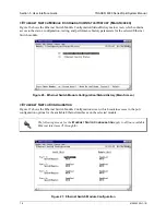
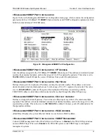
Figure 27 shows the Ethernet Switch Module Configuration screen, which contains access to the port
configuration options for the available Ethernet interfaces on the selected module.
Figure 27. Ethernet Switch Module Configuration
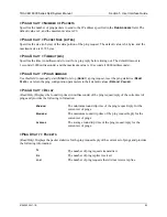
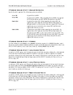
The following menus for the
E
THERNET
S
WITCH
C
ONFIGURATION
apply to all four available
Ethernet interfaces (
1
through
4
).
Содержание TRACER 6000 SERIES
Страница 10: ...Table of Contents TRACER 6000 Series Split System Manual 10 Copyright 2005 ADTRAN Inc 612806320L1 1B...
Страница 14: ...Section 1 System Description TRACER 6000 Series Split System Manual 14 Copyright 2005 ADTRAN Inc 612806320L1 1B...
Страница 88: ...Section 5 User Interface Guide TRACER 6000 Series Split System Manual 88 612806320L1 1B...
Страница 90: ...Section 6 Detail Level Procedures TRACER 6000 Series Split System Manual 90 612806320L1 1B...
Страница 98: ...Section 5 DLP 3 TRACER 6000 Series Split System Manual 98 Copyright 2005 ADTRAN Inc 612806320L1 1B...

