Section 5 User Interface Guide
TRACER 6000 Series Split System Manual
68
612806320L1-1B
> RF L
INK
M
IN
/M
AX
R
ECEIVED
S
IGNAL
Q
UALITY
H
ISTORY
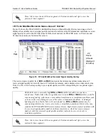
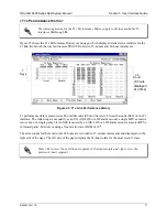
Figure 10 shows the TRACER RF Link Min/Max Received Signal Quality History menu page, which
displays the available received signal quality statistics from the system. Minimum and maximum received
signal quality levels for the RF link (from both the local and remote TRACER units) in 15-minute and
24-hour increments are found on this screen.
Figure 10. RF Link Min/Max Received Signal Quality History
The received power quality level (
MIN
and
MAX
) represents the minimum and maximum values of
received signal quality levels in 24-hour or 15-minute increments, and is displayed as a numerical value
from 0 to 100, with 0 corresponding to poor signal quality and 100 corresponding to exceptional signal
quality.
Press
<
n
>
to view the next 8-hour segment of 15-minute totals and
<
p
>
to view the
previous 8-hour segment.
Radio links with consistently high
MIN
and
MAX
numbers should not experience
interference. Radio links with a large difference between
MIN
and
MAX
numbers could be
experiencing fading, reflections, or intermittent interference or installation problems such
as loose connectors, damaged coax cable, water contaminated feedlines, or damaged
lightning arrestors. Radio links with consistently low
MIN
and
MAX
numbers may be
experiencing interference, low receive levels, or installation problems. If this is the case,
examine the RF link MIN/MAX received power history. High received power numbers with
low received signal quality numbers indicate interference, while low received power
numbers with low received signal quality numbers indicate low receive levels or
installation problems.
Press
<
n
>
to view the next 8-hour segment of 15-minute totals and
<
p
>
to view the
previous 8-hour segment.
7
Days
24
Hours
(8 hours
displayed
at a time)
Содержание TRACER 6000 SERIES
Страница 10: ...Table of Contents TRACER 6000 Series Split System Manual 10 Copyright 2005 ADTRAN Inc 612806320L1 1B...
Страница 14: ...Section 1 System Description TRACER 6000 Series Split System Manual 14 Copyright 2005 ADTRAN Inc 612806320L1 1B...
Страница 88: ...Section 5 User Interface Guide TRACER 6000 Series Split System Manual 88 612806320L1 1B...
Страница 90: ...Section 6 Detail Level Procedures TRACER 6000 Series Split System Manual 90 612806320L1 1B...
Страница 98: ...Section 5 DLP 3 TRACER 6000 Series Split System Manual 98 Copyright 2005 ADTRAN Inc 612806320L1 1B...

