Section 4 Network Turnup Procedure
TRACER 6000 Series Split System Manual
54
Copyright © 2005 ADTRAN, Inc.
612806320L1-1B
Quad E1 (75
Ω
) Module Interfaces
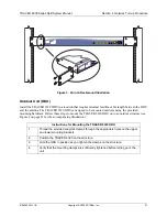
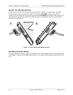
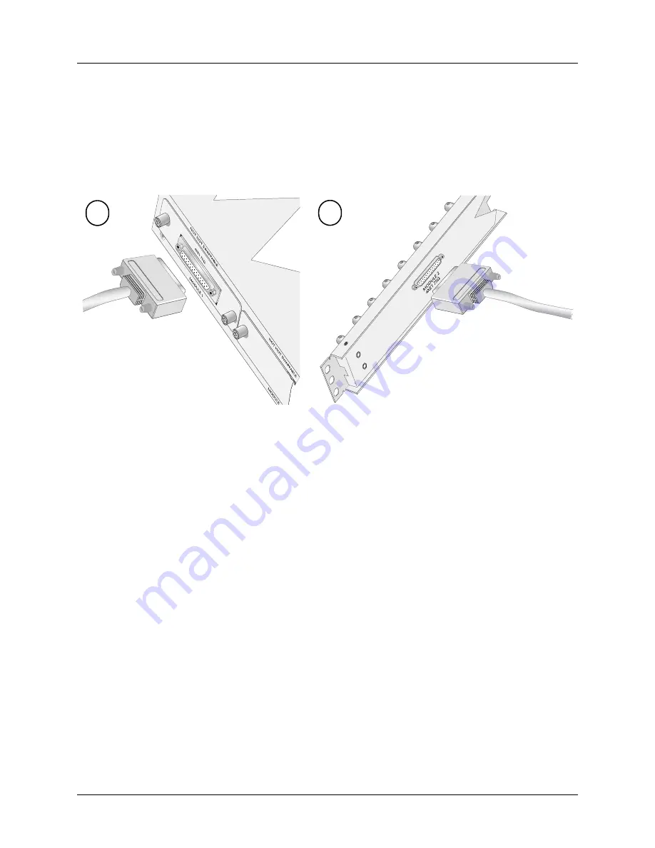
The physical E1 interfaces are provided using a single DB-25 interface, an adapter cable, and a BNC
breakout panel. Connect one end of the adapter cable (labeled
TO RADIO
) to the module’s DB-25
connector, and then attach the other end of the cable (labeled
TO PANEL
) to the BNC breakout panel. The
75
Ω
unbalanced interfaces provided by the breakout panel are available for connection to standard E1
DTE devices (see Figure 6).
Figure 6. E1 Connection with Breakout Panel
Quad Ethernet Switch Module
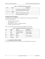
The physical Ethernet interfaces are provided using four RJ-45 jacks. Ethernet cables are not supplied with
your shipment. Connect any standard Ethernet device to one of the switch ports located on the rear of the
unit.
1
2
Содержание TRACER 6000 SERIES
Страница 10: ...Table of Contents TRACER 6000 Series Split System Manual 10 Copyright 2005 ADTRAN Inc 612806320L1 1B...
Страница 14: ...Section 1 System Description TRACER 6000 Series Split System Manual 14 Copyright 2005 ADTRAN Inc 612806320L1 1B...
Страница 88: ...Section 5 User Interface Guide TRACER 6000 Series Split System Manual 88 612806320L1 1B...
Страница 90: ...Section 6 Detail Level Procedures TRACER 6000 Series Split System Manual 90 612806320L1 1B...
Страница 98: ...Section 5 DLP 3 TRACER 6000 Series Split System Manual 98 Copyright 2005 ADTRAN Inc 612806320L1 1B...

