TRACER 6000 Series Split System Manual
Section 3 Engineering Guidelines
612806320L1-1B
Copyright © 2005 ADTRAN, Inc.
37
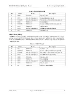
RSSI Monitoring Interface
The RSSI voltage is a function of the signal strength at the receiver and is used to measure the received
signal strength. RSSI varies from approximately 0 to 5 VDC. An RSSI calibration sheet is shipped with the
system to provide the installer a cross-reference between actual received signal level (in dBm) and RSSI
voltage. This sheet is useful for verifying link budget calculations and ensuring proper equipment
installation.
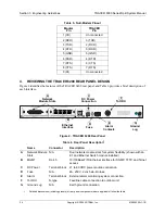
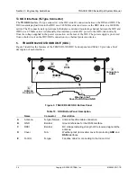
To IDU
The
TO IDU
interface (N-type connector) is the ODU-side IF connection between the IDU and ODU. The
ODU transmits payload data to the IDU on a 140 MHz carrier and receives the IDU data on a 280 MHz
carrier. The IF connection also provides a full-duplex control and monitoring channel between the IDU
and ODU on a 4.5 MHz carrier. Additionally, this interface accepts DC power from the IDU, taken directly
from the voltage supplied to the power connection on the rear of the IDU. The power supply is protected
from a short-circuit on the IDU/ODU connection via a thermal protection device.
6.
NETWORK MODULE INTERFACES
4xE1 Module with 120
Ω
Interface
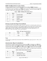
The 4xE1 network module provides four E1 interfaces (through four RJ-45 connectors) that provide the
following functions:
•
AMI or HDB3 coding
•
Framed, multi-framed, and unframed framing support
•
Network performance monitoring and reporting
•
Test loopbacks (both line and link)
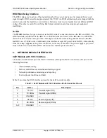
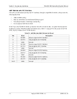
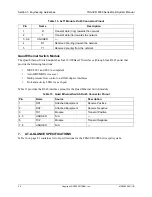
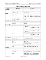
Table 11 provides the RJ-45 interface pinout for the 4xE1 network module.
Table 11. 4xE1 Module with 120
Ω
Interface RJ-45 Connector Pinout
Pin
Name
Description
1
TX TIP
Transmit signal (TIP)
2
TX RING
Transmit signal (RING)
3
UNUSED
—
4
RX TIP
Receive signal (TIP)
5
RX RING
Receive signal (RING)
6–8
UNUSED
—
Содержание TRACER 6000 SERIES
Страница 10: ...Table of Contents TRACER 6000 Series Split System Manual 10 Copyright 2005 ADTRAN Inc 612806320L1 1B...
Страница 14: ...Section 1 System Description TRACER 6000 Series Split System Manual 14 Copyright 2005 ADTRAN Inc 612806320L1 1B...
Страница 88: ...Section 5 User Interface Guide TRACER 6000 Series Split System Manual 88 612806320L1 1B...
Страница 90: ...Section 6 Detail Level Procedures TRACER 6000 Series Split System Manual 90 612806320L1 1B...
Страница 98: ...Section 5 DLP 3 TRACER 6000 Series Split System Manual 98 Copyright 2005 ADTRAN Inc 612806320L1 1B...

