


Hybrid Standalone NVR User Guide
4.7.2.2
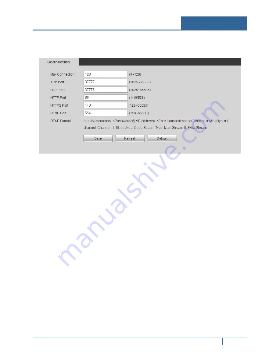
Connection
The connection screen is shown below in Figure 4-23.
Figure 4-23
Refer to the following for detailed information.
Max connection.
This setting is the maximum allowed web connections for one device. The value
ranges from 1 to 20. The default setup is 10.
TCP Port.
The default value is 37777. You can input the actual port number.
UDP Port.
The default value is 37778. You can input the actual port number.
HTTP Port.
The default value is 80. You can input the actual port number.
RTSP Port.
The default value is 554.
4.7.2.3
WIFI
This feature is not supported by ADT at this time.
4.7.2.4
3G
This feature is not supported by ADT at this time.
4.7.2.5
PPPoE
To set up PPPoE:
1.
Check the
Enable
box to enable the PPPoE feature.
2.
Input the PPPoE User Name and Password you get from the Internet Service Provider.
3.
Click
Save
.
4.
Reboot the device.
NVR32xx-P Series User Guide
156


