7
Accord xpC - July, 2001
Section 2:
Installing the Accord
XP
C
Ancillaries Pack
The Accord xpC control panel comes with an ancillaries pack. It contains ten zone links,
a cable clamp (with two self tapping screws), two M4×20 mm lid screws, battery connector
leads and 16 1K resistors.
Initial Mounting
Use the keyhole slot in the enclosure base to position the control panel enclosure. Three
mounting screws (not provided) are required to mount the enclosure base. Fix one of the
screws into the mounting surface, this will be used for the top, keyhole mounting hole.
Hang the enclosure base on the mounting screw ensuring that the screw sits in the nar-
row portion of the keyhole.
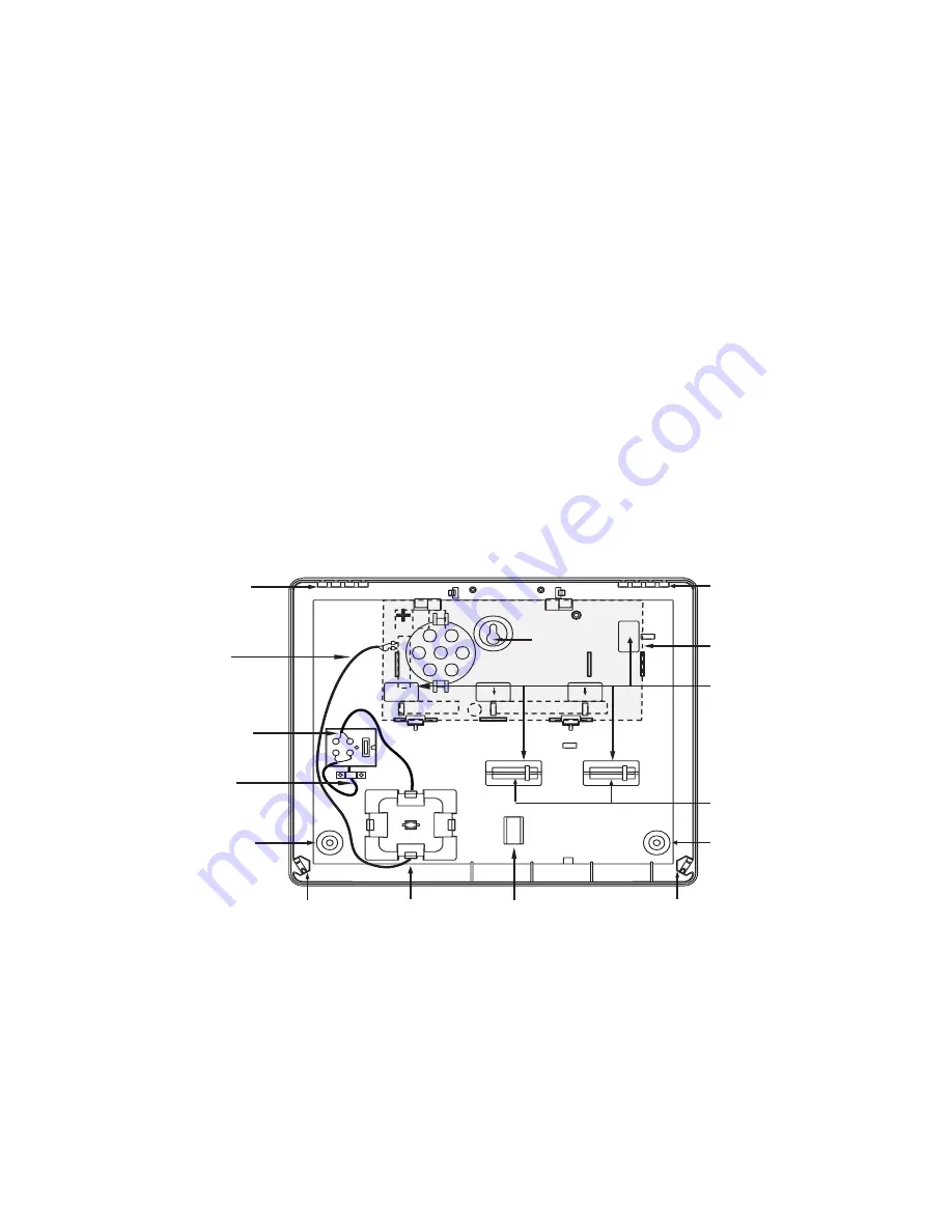
All cables should be brought into the enclosure base via the cable entry points shown in
figure 2.1. There are six cable entry holes for the entry of alarm cables. There is one a.c.
mains cable entry point located below the mains terminal block.
Figure 2.1 Accord
XP
C Enclosure Layout
Note: Leave about 60 mm above the control panel enclosure to enable the enclosure
lid to move on its hinges for removal and replacement.
Keyhole
Mounting
Slot
PCB Clip
PCB Clip
PCB
Lid Hinge
Recess
Cable Entry
Points
Transformer
Output
Transformer Output
Lead to PCB
Terminal Marked AC
Mains Terminal Block
with 200mA fuse.
See Connecting
Power to the System
Secure Mains
Cable After Feeding
Through Entry Point
User Instruction
retaining Clip
Lid Screw
Terminal
Lid Screw
Terminal
Mounting
Hole
Mounting
Hole
Lid Hinge
Recess
Knockout Tamper
Posts
Содержание ACCORD XPC
Страница 1: ...Installation Manual ...
Страница 2: ......
Страница 12: ...6 ...
Страница 48: ...42 ...
Страница 56: ...50 ...
Страница 61: ...55 Accord xpC July 2001 ...
Страница 62: ...56 IE1 1230 63 Issue D ...


