CHAPTER 4
RTU Network Configuration
239
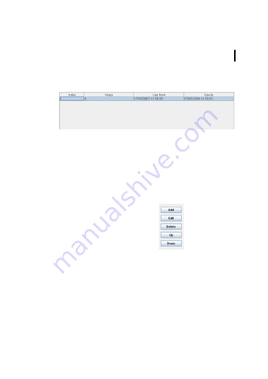
Routing Table
Figure 269. RTU - Routing Table
•
Index - current number in the routing table;
•
Hops - number of the hops required to reach the RTU
concerned;
•
Use from - time to start using the route;
•
Use to - time to end using the route.
Routing Buttons
Figure 270. RTU - Routing Buttons
•
“Add” button - allows to enter an additional router by use of
the “Route detail” window;
•
“Edit” button - allows to modify an existing router by use of
the “Route detail” window;
•
“Delete” button - allows to delete an existing router from the
routing order;
•
“Up” button - allows to change the routing order by shifting
singular routers upwards;
Содержание A850
Страница 92: ...CHAPTER 3 Configuring the Gateway 92 Figure 81 PPP Configuration Window ...
Страница 107: ...CHAPTER 3 107 Figure 101 SSH Tunnel Window The following window areas are available through the SSH tun nel window ...
Страница 128: ...CHAPTER 3 Configuring the Gateway 128 Figure 132 Dialup Modem Window ...
Страница 164: ...CHAPTER 3 Configuring the Gateway 164 ...
Страница 177: ...CHAPTER 4 Sensor Type Configuration 177 Figure 183 Sensor type Window Analog ...
Страница 196: ...CHAPTER 4 Using the Gateway 196 Figure 216 Sensor type Window LC ...
Страница 200: ...CHAPTER 4 Using the Gateway 200 Figure 222 Sensor type Window OC ...
Страница 204: ...CHAPTER 4 Using the Gateway 204 Figure 228 Sensor type Window SDI ...
Страница 215: ...CHAPTER 4 Logs 215 Figure 241 System Log Selection Log types Figure 242 System Log Log types ...
Страница 275: ...CHAPTER 4 RTU Network Configuration 275 Sensor details Figure 319 Sensor details Window ...
Страница 366: ...CHAPTER 6 Appendix 366 ...


