Chapter 1
4
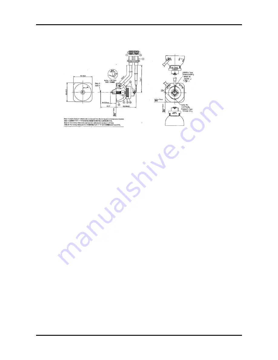
2.6 Lamp
& Ballaster
drawing
1. The lamp becomes high temperature after turning off the projector with the power
button. If you touch the lamp, you may scald your finger. When you replace the lamp,
wait for at least 45 minutes for the lamp to cool down.
2. Do not touch the lamp glass at any time. The lamp may explode due to improper
handling, including the touching of the lamp glass.
3. Lamp lifetime may differ from lamp to lamp and according to the environment of use.
There is no guarantee of the same lifetime for each lamp. Some lamps may fail or
terminate their lifetime in a shorter period of time than other similar lamps.
4. A lamp may explode as a result of vibration, shock or degradation as a result of hours
of use as its lifetime draws to an end. Risk of explosion may differ according to the
environment or conditions in which the projector and lamp are being used.
5. Wear protective gloves and eyeglasses when fixing or detaching the lamp.
6. Faster on-off-cycles will damage the lamp and reduce lamp life. Wait at least for 5
minutes to turn off the projector after powering on.
7. Do not operate the lamp in proximity to paper, cloth, or other combustible material nor
cover it with such materials. Otherwise it could cause a fire.
2.7 Instructions for use
Содержание PD-115
Страница 12: ...Chapter 1 6 System Block Diagram ...
Страница 13: ...7 Chapter 1 Optics Conceptual Drawing ...
Страница 21: ...15 Chapter 3 Disassemble Front Fan 1 Lift up the Front f Fan Set from front cover directly ...
Страница 27: ...21 Chapter 3 Disassemble Back Cover 1 Loosen the screw of AC Inlet remove the ring 2 Remove the Back Cover ...
Страница 28: ...Chapter 3 22 Disassemble Back IR Cover AC Outlet 1 Take out theAC Inlet 2 Take out the Back IR Cover ...
Страница 30: ...Chapter 3 24 Disassemble Mylar Ground Plate 1 Lift up the Mylar 2 Then lift up the Groung Plate ...
Страница 32: ...Chapter 3 26 Disassemble DMD Assembly DMD 1 Lift up the DMDAssembly 2 Lift up the DMD ...
Страница 33: ...27 Chapter 3 Disassemble Thermal Board 1 Loosen the screw of SENSOR BRACKET TPD 2 Remove the Thermal Borad ...
Страница 34: ...Chapter 3 28 Disassemble Optical Engine Fan 1 Loosen the three screws of Fan 2 Remove the Optical Engine Fan ...
Страница 41: ...Chapter 4 36 Function Test and Alignment Equipment Needed Test Condition ...
Страница 47: ...Chapter 5 42 CN2 Keypad Control ...
Страница 48: ...43 Chapter 5 CON2 Video CON3 S Video J3 J15 Video S Videop IN ...
Страница 49: ...Chapter 5 44 J7 Phone jack Stereo R CON1 D_SUB J8 Color Wheel ...
Страница 50: ...45 Chapter 5 JP1 USB J9 Power Supply JP3 CW Index JP3 CW Index ...
Страница 51: ...46 Chapter 5 Power Board Summarize The Locations of Connectors CN101 AC Inout ...
Страница 52: ...Chapter 5 47 CN201 380V Output CN301 DC Output ...
Страница 53: ...48 Chapter 5 Ballaster Board Summarize CN2 Control signal CN1 Power supply The Locations of Connectors ...
Страница 55: ...50 Chapter 6 FRU List ...
Страница 56: ...Chapter 6 51 ...
Страница 57: ...52 Chapter 6 ...
Страница 58: ...Chapter 6 53 ...


