35
Chapter 4
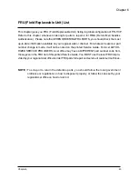
No Power Source
After Turning On
Check
Lamp Cover
Switch
Replace Lamp
Cover or
Reassembly
Check
Power Cord
Check
Top Cover (key
cable..)
Replace
cable or key
Check
Power
Board
Replace Main
Board
OK
NG
OK
OK
OK
NG
NG
NG
Replace
Power Board
NG
OK
Check
Main
Board
Power Source:
Replace Standby
Signal cable NG
Fan failure After
Turning On
Check
Fan
Connector
Fan Connector
Become loose
Check
Inner
Wires
Replace Inner
Wires
Check
Fan
R e p l a c e
Fan
Check
Main
Board
Replace
Main Board
OK
NG
OK
OK
NG
NG
NG
OK
R ep l ac e P o w e r
Baord
Replace
Power Cord
Содержание PD-115
Страница 12: ...Chapter 1 6 System Block Diagram ...
Страница 13: ...7 Chapter 1 Optics Conceptual Drawing ...
Страница 21: ...15 Chapter 3 Disassemble Front Fan 1 Lift up the Front f Fan Set from front cover directly ...
Страница 27: ...21 Chapter 3 Disassemble Back Cover 1 Loosen the screw of AC Inlet remove the ring 2 Remove the Back Cover ...
Страница 28: ...Chapter 3 22 Disassemble Back IR Cover AC Outlet 1 Take out theAC Inlet 2 Take out the Back IR Cover ...
Страница 30: ...Chapter 3 24 Disassemble Mylar Ground Plate 1 Lift up the Mylar 2 Then lift up the Groung Plate ...
Страница 32: ...Chapter 3 26 Disassemble DMD Assembly DMD 1 Lift up the DMDAssembly 2 Lift up the DMD ...
Страница 33: ...27 Chapter 3 Disassemble Thermal Board 1 Loosen the screw of SENSOR BRACKET TPD 2 Remove the Thermal Borad ...
Страница 34: ...Chapter 3 28 Disassemble Optical Engine Fan 1 Loosen the three screws of Fan 2 Remove the Optical Engine Fan ...
Страница 41: ...Chapter 4 36 Function Test and Alignment Equipment Needed Test Condition ...
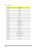
Страница 47: ...Chapter 5 42 CN2 Keypad Control ...
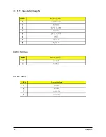
Страница 48: ...43 Chapter 5 CON2 Video CON3 S Video J3 J15 Video S Videop IN ...
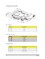
Страница 49: ...Chapter 5 44 J7 Phone jack Stereo R CON1 D_SUB J8 Color Wheel ...
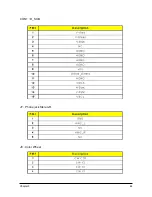
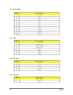
Страница 50: ...45 Chapter 5 JP1 USB J9 Power Supply JP3 CW Index JP3 CW Index ...
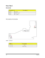
Страница 51: ...46 Chapter 5 Power Board Summarize The Locations of Connectors CN101 AC Inout ...
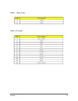
Страница 52: ...Chapter 5 47 CN201 380V Output CN301 DC Output ...
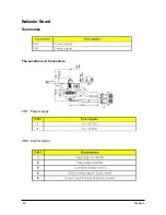
Страница 53: ...48 Chapter 5 Ballaster Board Summarize CN2 Control signal CN1 Power supply The Locations of Connectors ...
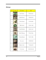
Страница 55: ...50 Chapter 6 FRU List ...
Страница 56: ...Chapter 6 51 ...
Страница 57: ...52 Chapter 6 ...
Страница 58: ...Chapter 6 53 ...


