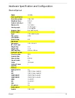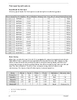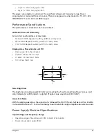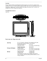
Chapter 2
43
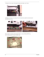
11.
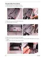
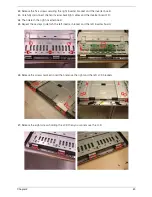
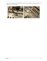
Release the four screws holding the I/O board.
12.
Then detach the I/O board as the arrow indicates.
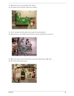
13.
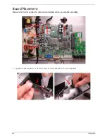
At first disconnect all the cables that connect to the main board.
14.
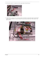
Release the four screws fastening the main board then detach the main board.
15.
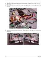
Release the eight screws fastening the power board and the grounded wire.
16.
Then remove the power board.
Содержание AT4220
Страница 10: ...4 Chapter 1 LCD Main Board Block Diagram ...
Страница 25: ...Chapter 1 19 For AT4220B Y Yellow Red White Blue Green R W 6 YLGHR 6 ...
Страница 28: ...22 Chapter 1 For AT4220B For AT4220 ...
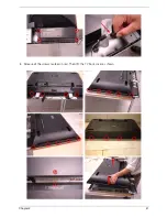
Страница 47: ...Chapter 2 41 8 Release all the screws marked in red Then lift the TV back cover as shown ...
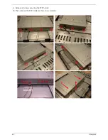
Страница 48: ...42 Chapter 2 9 Release all screws securing the PCB holder 10 Then remove the PCB holder as the arrows indicate ...
Страница 56: ...50 Chapter 2 ...

