System Utilities
2-11
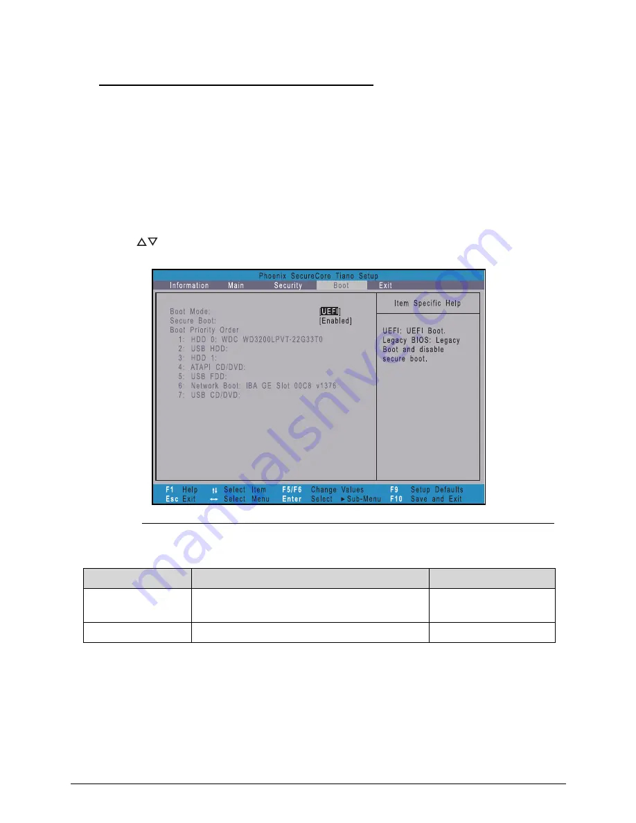
Boot
0
Use this tab to set the preferred drive sequence in which the
Setup Utility
attempts to boot the
operating system. By default, the computer searches for boot devices in the following order:
1.
Hard disk drive
2.
Optical disc drive
3.
Network boot
4.
External USB hard drive
5.
External USB optical drive
6.
External USB bootable device
Press
to select a device and press
F5
or
F6
to move it up or down the list.
Figure 2-8.
BIOS Boot
Table 2-8.
BIOS Boot
Parameter
Description
Option
Boot Mode
Option to specify the boot mode of the
computer.
UEFI or Legacy BIOS
Secure Boot
Option to enable or disable secure boot check.
Enabled or Disabled
Содержание Aspire V5-571P
Страница 1: ...Aspire V5 571PG V5 571P SERVICEGUIDE ...
Страница 9: ...CHAPTER 1 Hardware Specifications ...
Страница 12: ...1 4 ...
Страница 29: ...Hardware Specifications and Configurations 1 21 System Block Diagram 0 Figure 1 11 System Block Diagram ...
Страница 71: ...CHAPTER 2 System Utilities ...
Страница 92: ...2 22 System Utilities ...
Страница 93: ...CHAPTER 3 Machine Maintenance ...
Страница 96: ...3 4 ...
Страница 109: ...Machine Maintenance 3 17 6 Pry the ODD bezel off the module Figure 3 16 ODD Bezel ...
Страница 128: ...3 36 Machine Maintenance 4 Gently lift and detach the thermal module from the mainboard Figure 3 50 Thermal Module ...
Страница 143: ...Machine Maintenance 3 51 4 Gently pry the microphone off the LCD module Figure 3 76 Microphone ...
Страница 153: ...Machine Maintenance 3 61 3 Connect the microphone cable to the LCD FPC cable Figure 3 93 Microphone Cable ...
Страница 155: ...Machine Maintenance 3 63 3 Gently place the camera board into its socket in the LCD back cover Figure 3 96 Camera Board ...
Страница 167: ...Machine Maintenance 3 75 3 Connect the thermal module fan cable to the mainboard Figure 3 118 Fan Cable ...
Страница 172: ...3 80 Machine Maintenance 11 Connect the speaker cable to the mainboard Figure 3 127 Speaker Cable ...
Страница 194: ...3 102 Machine Maintenance ...
Страница 195: ...CHAPTER 4 Troubleshooting ...
Страница 225: ...CHAPTER 5 Jumper and Connector Locations ...
Страница 232: ...5 8 Jumper and Connector Locations ...
Страница 233: ...CHAPTER 6 FRU List ...
Страница 234: ...6 2 Aspire V5 571PG V5 571P 6 4 Exploded Diagrams 6 4 Main Assembly 6 4 LCD Assembly 6 6 FRU List 6 7 ...
Страница 251: ...CHAPTER 7 Test Compatible Components ...
Страница 252: ...7 2 Microsoft Windows 8 Environment Test 7 3 ...
Страница 265: ...CHAPTER 8 Online Support Information ...
Страница 266: ...8 2 Online Support Information 8 3 ...
Страница 268: ...8 4 Online Support Information ...


