Hardware Specifications and Configurations
1-19
Hotkeys
0
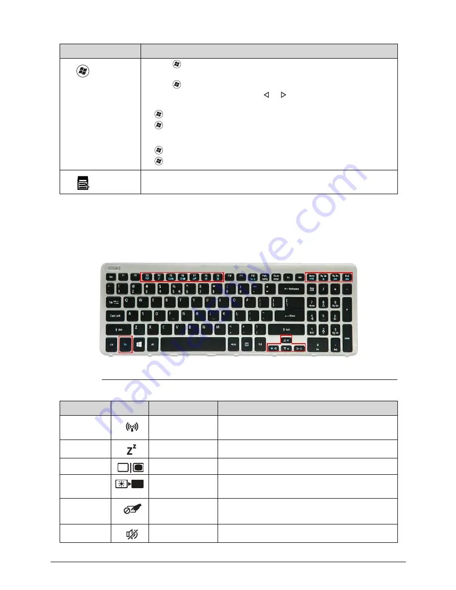
The computer uses hotkeys or key combinations to access most computer controls. To
activate hotkeys, press and hold the
Fn
key before pressing the key in the combination.
Figure 1-10.
Hotkeys
Windows
Logo key
Ctrl
+
+
L
: Lock your computer (if you are connected to a network
domain), or switch users (if you're not connected to a network domain)
Ctrl
+
+
Tab
: Moves focus from
Start
menu, to the
Quick Launch
toolbar, to the system tray (use or to move focus to items on the
Quick Launch
toolbar and the system tray)
+
Tab
: Cycle through programs on the taskbar
+
Break
: Display the
System Properties
dialog box
Functions supported by Windows XP:
+
Break
: Display the
System Properties
dialog box
+
U
: Open the
Ease of Access Center
window
Application
key
This key has the same effect as clicking the right mouse button; it opens
the application's context menu.
Hotkey
Icon
Function
Description
Fn
+
F3
Communication
device toggle
Toggles the WiFi function On and Off using a
pop-up window.
Fn
+
F4
Sleep
Puts the computer in Sleep mode.
Fn
+
F5
Display off
Turns off the LCD back light
Fn
+
F6
Display toggle
Switches the display output between the display
screen, external monitor (if connected) or both.
Fn
+
F7
Touchpad
toggle
Turns the touchpad On or Off.
Fn
+
F8
Speaker toggle
Turns the speakers On or Off.
Key
Description
Содержание Aspire V5-571P
Страница 1: ...Aspire V5 571PG V5 571P SERVICEGUIDE ...
Страница 9: ...CHAPTER 1 Hardware Specifications ...
Страница 12: ...1 4 ...
Страница 29: ...Hardware Specifications and Configurations 1 21 System Block Diagram 0 Figure 1 11 System Block Diagram ...
Страница 71: ...CHAPTER 2 System Utilities ...
Страница 92: ...2 22 System Utilities ...
Страница 93: ...CHAPTER 3 Machine Maintenance ...
Страница 96: ...3 4 ...
Страница 109: ...Machine Maintenance 3 17 6 Pry the ODD bezel off the module Figure 3 16 ODD Bezel ...
Страница 128: ...3 36 Machine Maintenance 4 Gently lift and detach the thermal module from the mainboard Figure 3 50 Thermal Module ...
Страница 143: ...Machine Maintenance 3 51 4 Gently pry the microphone off the LCD module Figure 3 76 Microphone ...
Страница 153: ...Machine Maintenance 3 61 3 Connect the microphone cable to the LCD FPC cable Figure 3 93 Microphone Cable ...
Страница 155: ...Machine Maintenance 3 63 3 Gently place the camera board into its socket in the LCD back cover Figure 3 96 Camera Board ...
Страница 167: ...Machine Maintenance 3 75 3 Connect the thermal module fan cable to the mainboard Figure 3 118 Fan Cable ...
Страница 172: ...3 80 Machine Maintenance 11 Connect the speaker cable to the mainboard Figure 3 127 Speaker Cable ...
Страница 194: ...3 102 Machine Maintenance ...
Страница 195: ...CHAPTER 4 Troubleshooting ...
Страница 225: ...CHAPTER 5 Jumper and Connector Locations ...
Страница 232: ...5 8 Jumper and Connector Locations ...
Страница 233: ...CHAPTER 6 FRU List ...
Страница 234: ...6 2 Aspire V5 571PG V5 571P 6 4 Exploded Diagrams 6 4 Main Assembly 6 4 LCD Assembly 6 6 FRU List 6 7 ...
Страница 251: ...CHAPTER 7 Test Compatible Components ...
Страница 252: ...7 2 Microsoft Windows 8 Environment Test 7 3 ...
Страница 265: ...CHAPTER 8 Online Support Information ...
Страница 266: ...8 2 Online Support Information 8 3 ...
Страница 268: ...8 4 Online Support Information ...


