1-18
Hardware Specifications and Configurations
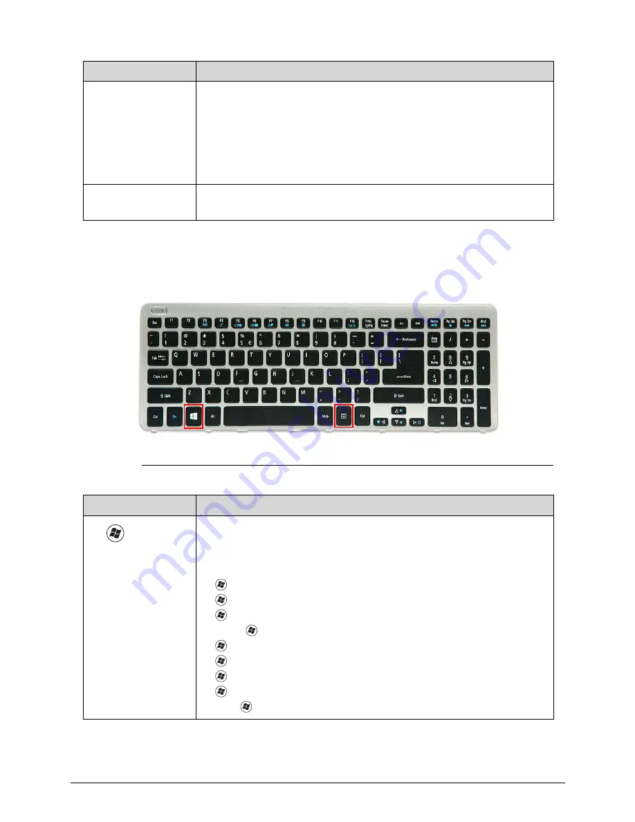
Windows Keys
0
The keyboard has two keys that perform Windows-specific functions.
Figure 1-9.
Windows-specific Keys
Num Lock
The key can be turned on/off via the internal keyboard (
Fn
+
F11
) or the
external keyboard/keypad. Num Lock affects the external
keyboard/keypad only.
Shift state is NOT required for the cursor movement by the numeric
keys.
The state of the Num Lock is not changed by the attachment/removal
(hot plug) of the external keyboard/keypad.
Scroll Lock
Fn
+
F12
When On, the screen moves one line up or down when pressing the up
or down cursor keys. Scroll Lock is not applicable for all applications.
Key
Description
Windows
Logo key
Pressed alone, this key has the same effect as clicking on the
Windows
Start
button; it launches the
Start
menu. It can also be used with other
keys to provide a variety of functions.
Functions supported by Windows XP, Windows Vista, and Windows 7 & 8:
: Open or close the
Start
menu
+
R
: Open the
Run
dialog box
+
M
: Minimizes all windows
Shift
+
+
M
: Restore minimized windows to the desktop
+
F1
: Show the
Help
window
+
E
: Open
Windows Explorer
+
F
: Search for a file or folder
+
D
: Display the desktop
Ctrl
+
+
F
: Search for computers (if you are on a network)
Lock Key
Description
Содержание Aspire V5-571P
Страница 1: ...Aspire V5 571PG V5 571P SERVICEGUIDE ...
Страница 9: ...CHAPTER 1 Hardware Specifications ...
Страница 12: ...1 4 ...
Страница 29: ...Hardware Specifications and Configurations 1 21 System Block Diagram 0 Figure 1 11 System Block Diagram ...
Страница 71: ...CHAPTER 2 System Utilities ...
Страница 92: ...2 22 System Utilities ...
Страница 93: ...CHAPTER 3 Machine Maintenance ...
Страница 96: ...3 4 ...
Страница 109: ...Machine Maintenance 3 17 6 Pry the ODD bezel off the module Figure 3 16 ODD Bezel ...
Страница 128: ...3 36 Machine Maintenance 4 Gently lift and detach the thermal module from the mainboard Figure 3 50 Thermal Module ...
Страница 143: ...Machine Maintenance 3 51 4 Gently pry the microphone off the LCD module Figure 3 76 Microphone ...
Страница 153: ...Machine Maintenance 3 61 3 Connect the microphone cable to the LCD FPC cable Figure 3 93 Microphone Cable ...
Страница 155: ...Machine Maintenance 3 63 3 Gently place the camera board into its socket in the LCD back cover Figure 3 96 Camera Board ...
Страница 167: ...Machine Maintenance 3 75 3 Connect the thermal module fan cable to the mainboard Figure 3 118 Fan Cable ...
Страница 172: ...3 80 Machine Maintenance 11 Connect the speaker cable to the mainboard Figure 3 127 Speaker Cable ...
Страница 194: ...3 102 Machine Maintenance ...
Страница 195: ...CHAPTER 4 Troubleshooting ...
Страница 225: ...CHAPTER 5 Jumper and Connector Locations ...
Страница 232: ...5 8 Jumper and Connector Locations ...
Страница 233: ...CHAPTER 6 FRU List ...
Страница 234: ...6 2 Aspire V5 571PG V5 571P 6 4 Exploded Diagrams 6 4 Main Assembly 6 4 LCD Assembly 6 6 FRU List 6 7 ...
Страница 251: ...CHAPTER 7 Test Compatible Components ...
Страница 252: ...7 2 Microsoft Windows 8 Environment Test 7 3 ...
Страница 265: ...CHAPTER 8 Online Support Information ...
Страница 266: ...8 2 Online Support Information 8 3 ...
Страница 268: ...8 4 Online Support Information ...


