24
Chapter 2
Changing a Password
1.
Use the
↑
and
↓
keys to highlight the Set Supervisor Password parameter and press the
Enter
key. The
Set Password box appears.
2.
Type the current password in the Enter Current Password field and press
Enter
.
3.
Type a password in the Enter New Password field. Retype the password in the Confirm New Password
field.
4.
Press
Enter
. After setting the password, the computer sets the User Password parameter to “Set”.
5.
If desired, you can enable the Password on boot parameter.
6.
When you are done, press
F10
to save the changes and exit the BIOS Setup Utility.
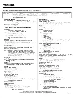
If the verification is OK, the screen will display as following.
The password setting is complete after the user presses
Enter
.
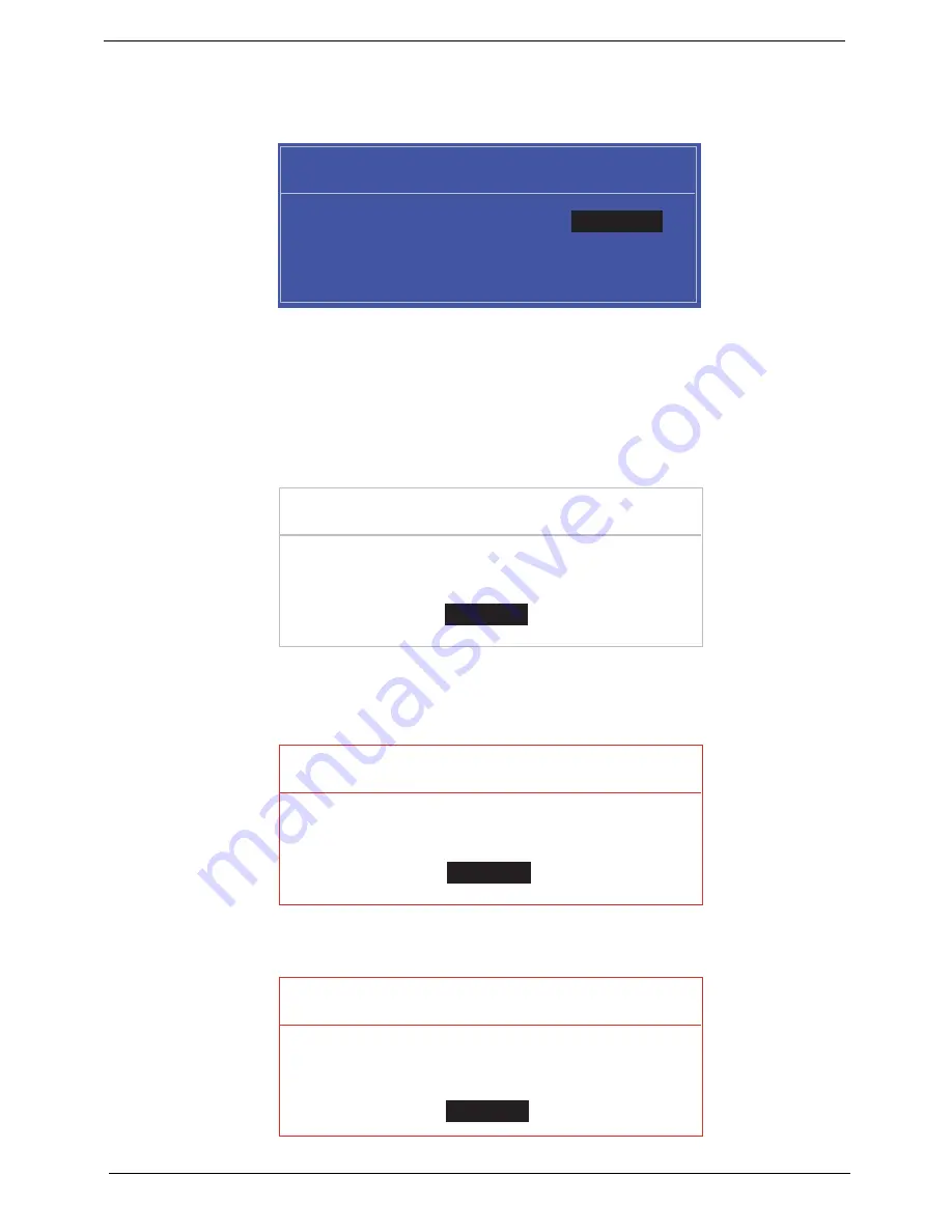
If the current password entered does not match the actual current password, the screen will show you the
Setup Warning.
If the new password and confirm new password strings do not match, the screen displays the following
message.
S e t S u p e r v i s o r P a s s w o r d
E n t e r C u r r e n t P a s s w o r d [ ]
[ ]
E n t e r N e w P a s s w o r d [ ]
C o n f i r m N e w P a s s w o r d [ ]
[ ]
S e t u p N o t i c e
C h a n g e s h a v e b e e n s a v e d .
[ C o n t i n u e ]
[
C o n t i n u e
]
S e t u p W a r n i n g
I n v a l i d P a s s w o r d .
[ C o n t i n u e ]
[
C o n t i n u e
]
S e t u p W a r n i n g
P a s s w o r d s d o n o t m a t c h .
R e - e n t e r p a s s w o r d .
[ C o n t i n u e ]
[
C o n t i n u e
]
Содержание Aspire One AOP531h
Страница 6: ...VI ...
Страница 10: ...X Table of Contents ...
Страница 41: ...Chapter 2 31 Clear User or Supervisor Password 1 Open the RAM door 2 Short RTC_RST ...
Страница 54: ...44 Chapter 3 Removing the SIMM card 1 Press the SIMM card in to eject it 2 Pull the card out from the slot ...
Страница 62: ...52 Chapter 3 7 Lift the Keyboard FFC securing latch as shown 8 Disconnect the FFC and remove the Keyboard ...
Страница 83: ...Chapter 3 73 Pull the cable completely away from the bezel ...
Страница 93: ...Chapter 3 83 Replacing the Camera Board 1 Reconnect the connector as shown 2 Place the camera pcb ...
Страница 95: ...Chapter 3 85 4 Replace the four screws and screw caps ...
Страница 107: ...Chapter 3 97 The upper cover is now ready to attach to the bottom cover ...
Страница 109: ...Chapter 3 99 Turn the unit over and affix the five screws in the top cover ...
Страница 115: ...Chapter 3 105 Replacing the SIMM Card Insert the SIMM Card into the slot ...
Страница 130: ...120 Chapter 4 ...
Страница 138: ...128 Chapter 4 ...
Страница 152: ...142 Chapter 6 ...
Страница 153: ...Chapter 6 143 ...
Страница 267: ...257 Appendix A ...
Страница 268: ...Appendix A 258 ...
Страница 274: ...264 Appendix B ...
Страница 276: ...266 Appendix C ...
Страница 279: ...269 W Windows 2000 Environment Test 260 Wireless Function Failure 119 WLAN Antennas Removing 77 Replacing 79 ...
Страница 280: ...270 ...