


22
Chapter 2
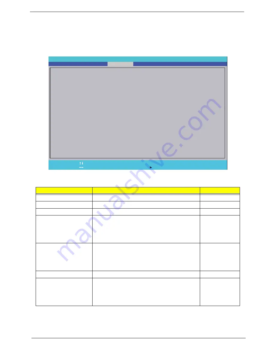
Security
The Security screen contains parameters that help safeguard and protect your computer from unauthorized
use.
The table below describes the parameters in this screen. Settings in
boldface
are the default and suggested
parameter settings.
NOTE:
When you are prompted to enter a password, you have three tries before the system halts.
Parameter
Description
Option
Supervisor Password Is
Shows the setting of the Supervisor password
Clear
or Set
User Password Is
Shows the setting of the User password.
Clear
or Set
HDD Password Is
Shows the setting of the HDD password.
Clear
or Set
Set Supervisor Password
Press Enter to set the supervisor password. When
set, this password protects the BIOS Setup Utility
from unauthorized access. The user can not either
enter the Setup menu nor change the value of
parameters.
Set User Password
Press Enter to set the user password. When user
password is set, this password protects the BIOS
Setup Utility from unauthorized access. The user can
enter Setup menu only and does not have right to
change the value of parameters.
Set Hdd Password
Enter HDD password.
Power on password
Defines whether a password is required or not while
the events defined in this group happened. The
following sub-options are all requires the Supervisor
password for changes and should be grayed out if the
user password was used to enter setup.
Enabled or
Disabled
InsydeH2O Se t u p U t i l i t y
S u p e r v i s o r P a s s o w r d :
U s e r P a s s w o r d :
S e t S u p e r v i s o r P a s s w o r d
S e t U s e r P a s s w o r d
S e t H d d P a s s w o r d
P o w e r o n p a s s w o r d
[ D i s a b l e ]
C l e a r
C l e a r
H D D P a s s w o r d I s :
C l e a r
F1
Es c
H e l p
E x i t
S e l e c t I t e m
S e l e c t M e n u
C h a n g e Va l u e s
S e l e c t
S u b - M e n u
-/+
Ente r
F9
F1 0
S e t u p D e f a u l t s
S a v e a n d E x i t
I n f o r m a t i o n
S e c u r i t y
B o o t
E x i t
M a i n
Содержание Aspire One AOP531h
Страница 6: ...VI ...
Страница 10: ...X Table of Contents ...
Страница 41: ...Chapter 2 31 Clear User or Supervisor Password 1 Open the RAM door 2 Short RTC_RST ...
Страница 54: ...44 Chapter 3 Removing the SIMM card 1 Press the SIMM card in to eject it 2 Pull the card out from the slot ...
Страница 62: ...52 Chapter 3 7 Lift the Keyboard FFC securing latch as shown 8 Disconnect the FFC and remove the Keyboard ...
Страница 83: ...Chapter 3 73 Pull the cable completely away from the bezel ...
Страница 93: ...Chapter 3 83 Replacing the Camera Board 1 Reconnect the connector as shown 2 Place the camera pcb ...
Страница 95: ...Chapter 3 85 4 Replace the four screws and screw caps ...
Страница 107: ...Chapter 3 97 The upper cover is now ready to attach to the bottom cover ...
Страница 109: ...Chapter 3 99 Turn the unit over and affix the five screws in the top cover ...
Страница 115: ...Chapter 3 105 Replacing the SIMM Card Insert the SIMM Card into the slot ...
Страница 130: ...120 Chapter 4 ...
Страница 138: ...128 Chapter 4 ...
Страница 152: ...142 Chapter 6 ...
Страница 153: ...Chapter 6 143 ...
Страница 267: ...257 Appendix A ...
Страница 268: ...Appendix A 258 ...
Страница 274: ...264 Appendix B ...
Страница 276: ...266 Appendix C ...
Страница 279: ...269 W Windows 2000 Environment Test 260 Wireless Function Failure 119 WLAN Antennas Removing 77 Replacing 79 ...
Страница 280: ...270 ...


