Chapter 5
129
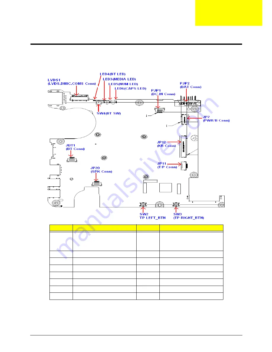
Jumper and Connector Locations
Top View
Item
Description
Item
Description
JLVDS1
LCD Connect
Internal camera Connector
Internal DMIC Connector
JP2
TO PWR/B Connector
LED4
Bluetooth LED
JP12
Internal Keyboard Connector
SW4
Bluetooth Button
JP11
Internal Track-Pad Connector
LED3
Media LED
SW3
Right Button
LED5
NUM LED
SW2
Left Button
LED6
CAP LED
JP20
Speaker Connector
PJP1
TO Power core Connector
JBT1
Bluetooth Connector
PJP2
Battery Connector
Chapter 5
Содержание Aspire One AOP531h
Страница 6: ...VI ...
Страница 10: ...X Table of Contents ...
Страница 41: ...Chapter 2 31 Clear User or Supervisor Password 1 Open the RAM door 2 Short RTC_RST ...
Страница 54: ...44 Chapter 3 Removing the SIMM card 1 Press the SIMM card in to eject it 2 Pull the card out from the slot ...
Страница 62: ...52 Chapter 3 7 Lift the Keyboard FFC securing latch as shown 8 Disconnect the FFC and remove the Keyboard ...
Страница 83: ...Chapter 3 73 Pull the cable completely away from the bezel ...
Страница 93: ...Chapter 3 83 Replacing the Camera Board 1 Reconnect the connector as shown 2 Place the camera pcb ...
Страница 95: ...Chapter 3 85 4 Replace the four screws and screw caps ...
Страница 107: ...Chapter 3 97 The upper cover is now ready to attach to the bottom cover ...
Страница 109: ...Chapter 3 99 Turn the unit over and affix the five screws in the top cover ...
Страница 115: ...Chapter 3 105 Replacing the SIMM Card Insert the SIMM Card into the slot ...
Страница 130: ...120 Chapter 4 ...
Страница 138: ...128 Chapter 4 ...
Страница 152: ...142 Chapter 6 ...
Страница 153: ...Chapter 6 143 ...
Страница 267: ...257 Appendix A ...
Страница 268: ...Appendix A 258 ...
Страница 274: ...264 Appendix B ...
Страница 276: ...266 Appendix C ...
Страница 279: ...269 W Windows 2000 Environment Test 260 Wireless Function Failure 119 WLAN Antennas Removing 77 Replacing 79 ...
Страница 280: ...270 ...


