Chapter 2
23
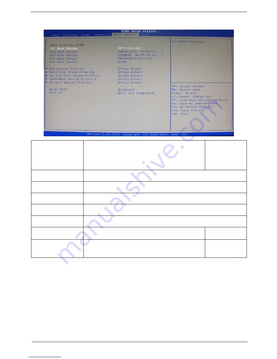
Boot Options
1st/2nd/3rd/4th/5th Boot
Device
Specifies the boot order from the available devices.
EFI
Hard Disk
CD^DVD
Removable Device
LAN
EFI Device Priority
Press
Enter
to access the EFI Device Priority submenu and specify the boot device priority
sequence from available EFI devices.
Hard Disk Drive Priority
Press
Enter
to access the Hard Disk Drive Priority submenu and specify the boot device
priority sequence from available hard drives.
Optical Disk Drive Priority
Press
Enter
to access the Optical Disk Drive Priority submenu and specify the boot device
priority sequence from available optical drives.
Removable Device Priority
Press
Enter
to access the Removable Device Priority submenu and specify the boot device
priority sequence from available removable drives.
Network Device Priority
Press
Enter
to access the Network Device Priority submenu and specify the boot device
priority sequence from available network drives.
Quiet Boot
When enabled, the BIOS splash screen displays during startup.
When disabled, the diagnostic screen displays during startup.
Enabled
Disabled
Halt On
Determines whether the system will stop for an error during the POST.
All,but keyboard
No Errors
All Errors
Содержание Aspire M3985
Страница 1: ...Acer Aspire M3985 Service Guide PRINTED IN TAIWAN ...
Страница 13: ...Chapter 1 5 Block Diagram ...
Страница 41: ...Chapter 3 33 Removing the VGA Card 1 Remove the screw that secures the card to the chassis 2 Open PCI Latch ...
Страница 46: ...38 Chapter 3 4 Pull the Pull the optical drive out of the chassis ...
Страница 50: ...42 Chapter 3 7 Lift the power supply module out of the chassis ...
Страница 53: ...Chapter 3 45 3 Lift the board from the chassis 4 Punching in IO Shield then you can remove it ...
Страница 68: ...60 Chapter 3 Reinstalling the Power Supply 1 Install the power supply to chassis 2 Fix the four screws ...
Страница 69: ...Chapter 3 61 Reinstalling the I O Shielding 1 Install I O shielding into chassis ...
Страница 77: ...Chapter 3 69 3 Close the PCI Latch fix the three screws ...
Страница 80: ...72 Chapter 3 3 Connect the cooler cable to the main board connector ...
Страница 82: ...74 Chapter 3 3 Make sure the front bezel retention tabs are securedly fastened to the chassis interior ...
Страница 83: ...Chapter 3 75 Reinstalling the Side Panel 1 Install the side Panel then fix two screws ...
Страница 91: ...83 Chapter 4 b Select Proceed with flash update and Press Enter ...


